Setup Mode
44 312776F
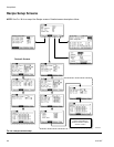
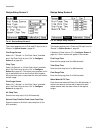
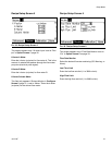
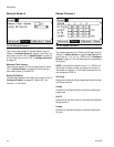
Recipe 0 Screen 3
This screen only appears if Solvent Monitor is set to
“Meter” in Configure Screen 5, page 31 and Flush Vol-
ume Check is set to “On” in Option Screen 1, page 32
or 3rd Flush Valve is set to “On” in Configure Screen 3
on page 30.
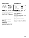
Minimum Flush Volume
This field only appears if Flush Volume Check is set to
“On” in Option Screen 1 on page 32. Enter the mini-
mum flush volume (0 to 9999 cc).
Exiting Fill Source
This field only appears if 3rd Flush Valve is set to “On” in
Configure Screen 3 on page 30. Select “Off,” “Air,”
“Solvent,” or “3rd Valve.”
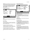
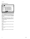
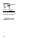
Recipe 0 Screen 4
This screen appears only if Flush and Fill Input is set to
“Recipe” in Option Screen 1, page 32 and Special Out-
puts is set to 1, 2, 3, 4, or “3 + GFB on #4” in Configure
Screen 5, page 31. The I/O board has four programma-
ble outputs.
NOTE: If the Special Outputs is set to “3 + GFB on #4”,
the Recipe 0 Screen 4 does not display the column of
information for Special 4. That Output assumes the val-
ues assigned to GFB #1.
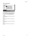
On-Purge
Delay time at the start of the purge cycle before the Spe-
cial Output turns on.
Length
Duration for the Special Output to be active during the
purge cycle.
On-Fill
Delay time at the start of the fill cycle before the Special
Output turns on.
Length
Duration for the Special Output to be active during the
fill cycle.
F
IG. 48. Recipe 0 Screen 3
FIG. 49. Recipe 0 Screen 4


