Color Change
312776F 75
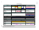
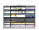
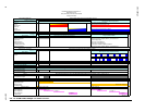
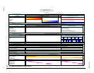
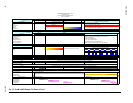
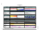
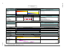
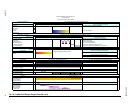
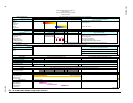
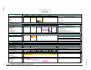
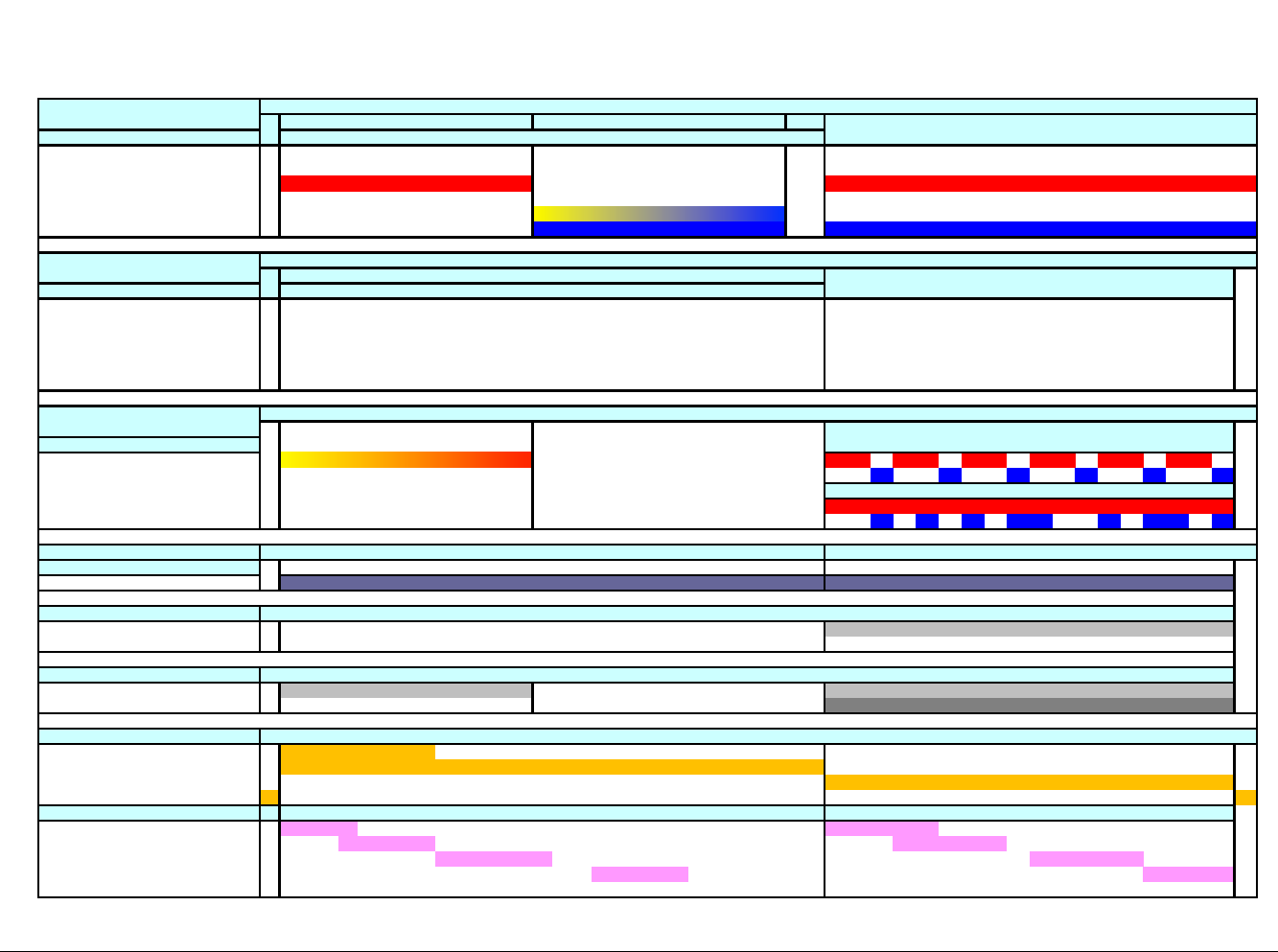
FIG. 76: ProMix 2KS Recipe Fill Chart #6 0 to Y
Color/Catalyst/(Reducer)
No Purge, Fill from Y -->
Stack Valves
Solvent A Only active components are filled
Dump A Push out solvent and fill with new color
Component A
Solvent B
Dump B Push out solvent and fill with new catalyst
Component B
Separate Gun 1 and Gun 2
No Purge -->
Purge Valves
First Purge Selection
Select Purge A (Air), Purge B (Solvent), or 3rd Valve on A
Purge A (Air) Fixed for Purge A (Air)
Purge B (Solvent) If Chop Type is "Air/Solvent"
3rd Purge Valve on A
If Chop Type is "Air/3rd Purge"
2 s B Purge after Chop Fixed Purge B. Enabled in Options Screen 2
Final Purge Selection Select Purge A (Air), Purge B (Solvent), or 3rd Valve on A
Separate Gun 1 and Gun 2
Fill from Y -->
Dose Valves
Dose A <- A Fill through Dose A with no Dump A
Dose B
GFB Outputs
If No Gun Flush Boxes
Gun Trigger(s) by Operator
1 Gun
Gun Flush Box Output 1
Gun Flush Box Output 2
2 Guns
Gun Flush Box Output 1
Gun Flush Box Output 2
Digital I/O
Color Change Input <- Start of Color Change
Purge Active Output
Fill Active Output End of Color Change ->
Mix Ready Output
Special Outputs <- Start of On-Purge
<- Start of On-Fill
Special Output #1 <- Length -> <- Length ->
Special Output #2 <- Length -> <- Length ->
Special Output #3 <- Length -> <- Length ->
Special Output #4 <- Length -> <- Length ->
3 + GFB on #4
2KS 0 to X K12
Discrete I/O Signals by Time
GFB 1 Only
Each Integrator Flush Purge, Chop, and Mix Material Fill operation runs sequentially for Gun 1 then for Gun 2
Mixed Fill Time using Sequential Dosing
Mixed Fill Time using Dynamic Dosing
Gun and Hose Flush Operations by Time Gun and Hose Mix Material Fill Operations by Time
This happens on the same time scale as the Dose Valve and Integrator Flush Sequence
Dose Valve and Integrator Flush Sequence Purge Operation Details
Dose Valve and Integrator Mix Fill Operations by Time
Dose Valve and Integrator Flush Purge and Chop Operations by Time
Waiting
No Dump A
ProMix 2KS Recipe Fill Chart #6 0 to Y
Stack Valves A1, B1
No Dump A, 3rd Flush Valve Enabled
No Exiting Fill
Color Change Stack Purge and Fill Operations by Time
A Fill B Fill
Color Change Stack Flush Sequence Color Change Stack Components


