


iv HP Omnibook 6000/6100
Figures
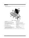
Figure 1-1. Omnibook — Front View..................................................................................................1-3
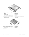
Figure 1-2. Omnibook — Back View ..................................................................................................1-4
Figure 1-3. Omnibook — Bottom View...............................................................................................1-4
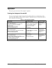
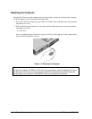
Figure 1-4. Resetting the Computer .....................................................................................................1-8
Figure 1-5. Replaceable Module Diagram .........................................................................................1-14
Figure 2-1. Disassembly Flow..............................................................................................................2-3
Figure 2-2. Removing the Battery........................................................................................................2-4
Figure 2-3. Removing a Module ..........................................................................................................2-5
Figure 2-4. Removing a Module ..........................................................................................................2-5
Figure 2-5. Removing a SDRAM Module...........................................................................................2-6
Figure 2-6. Removing the Hard Disk Drive .........................................................................................2-7
Figure 2-7. Removing the Hard Disk Case ..........................................................................................2-8
Figure 2-8. Removing the Mini-PCI Card..........................................................................................2-10
Figure 2-9. Removing the Power Button Panel..................................................................................2-11
Figure 2-10. Removing the Display ...................................................................................................2-14
Figure 2-11. Removing the Keyboard................................................................................................2-15
Figure 2-12. Unplugging the Keyboard Cables..................................................................................2-16
Figure 2-13. Removing the Heatsink..................................................................................................2-17
Figure 2-14. Removing the CPU Module...........................................................................................2-19
Figure 2-15. Removing the Top Case: Omnibook 6100 Models .......................................................2-22
Figure 2-16. Removing the Top Case: Omnibook 6000 Models .......................................................2-23
Figure 2-17. Removing the Motherboard: Omnibook 6100 Models..................................................2-25
Figure 2-18. Removing the Motherboard: Omnibook 6000 Models..................................................2-26
Figure 2-19. Installing Docking Doors...............................................................................................2-27
Figure 2-20. Installing the Lower PCMCIA Door .............................................................................2-27
Figure 2-21. Replacing Motherboard Components: Omnibook 6100 Models...................................2-29
Figure 2-22. Replacing Motherboard Components: Omnibook 6000 Models...................................2-30
Figure 2-23. Example of Serial Number Label ..................................................................................2-32
Figure 2-24. Boot-Block Jumper........................................................................................................2-34
Figure 3-1. Basic Troubleshooting Steps .............................................................................................3-2
Figure 3-2. Diagnostic Screens — Basic and Advanced....................................................................3-17
Figure 3-3. Serial and Parallel Loopback Connectors........................................................................3-19
Figure 4-1. Exploded View ..................................................................................................................4-2