


2-34 Removal and Replacement HP Omnibook 6000/6100
14
1
25
1
3
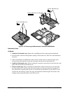
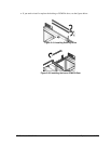
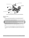
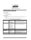
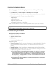
Figure 2-24. Boot-Block Jumper
Removing Other Components
(HP Authorized Service Providers Only)
Required Equipment
• Small Phillips screwdriver.
• Small flat-blade screwdriver.
Removal Procedure
1. Unplug the AC adapter, if present, and remove the battery. Remove the secondary battery if one is
installed.
2. Remove the assemblies and follow the additional steps given in the table below.
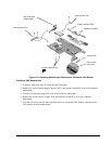
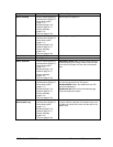
Table 2-6. Removing Omnibook Components
Component Removal Procedure Additional Steps
Battery, CMOS
Power button panel
(page 2-11).
Keyboard (page 2-15).
Heatsink (page 2-17).
Reassembly Notes: After replacing the CMOS
battery, set the correct time and date using the BIOS
Setup utility or Date/Time in the Control Panel.
Card, mini-PCI #2
(Omnibook 6100 only)
Plug-in module (page 2-5).
Hard disk drive (page 2-7).
Power button panel
(page 2-11).
Keyboard (page 2-15).
Heatsink (page 2-17).
Display assembly
(page 2-13).
Top case (page 2-20).
Motherboard (page 2-24).
The card is attached to bottom side of the
motherboard. Release the two latches at the sides of
the card so the free edge of the board pops up.
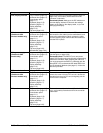
Case, bottom
See page 2-22.
Case, top
See page 2-20.
Covers, hinge (left,
right, or center)
Power button panel
(page 2-11).
Display assembly
(page 2-13).
Caution: When removing the center hinge cover, be
careful not to pull on or damage the display cable.
Reassembly Notes: Make sure the center hinge cover
fits over the tab in the bottom case.
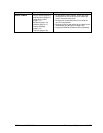
CPU module
See page 2-19.
Display assembly
See page 2-13.