


HP Omnibook 6000/6100 Removal and Replacement 2-35
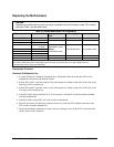
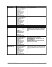
Component Removal Procedure Additional Steps
Doors, docking
Plug-in module (page 2-5).
Hard disk drive (page 2-7).
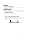
Power button panel
(page 2-11).
Keyboard (page 2-15).
Heatsink (page 2-17).
Display assembly
(page 2-13).
Top case (page 2-20).
See the figure on page 2-27.
Doors, PCMCIA
Plug-in module (page 2-5).
Hard disk drive (page 2-7).
Power button panel
(page 2-11).
Keyboard (page 2-15).
Heatsink (page 2-17).
Display assembly
(page 2-13).
Top case (page 2-20).
See the figure on page 2-27.
Heatsink (with fan)
See page 2-17.
Keyboard
See page 2-15.
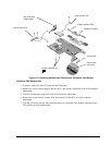
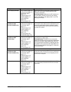
Panel, sound/IR
Plug-in module (page 2-5).
Hard disk drive (page 2-7).
Power button panel
(page 2-11).
Keyboard (page 2-15).
Heatsink (page 2-17).
Display assembly
(page 2-13).
Top case (page 2-20).
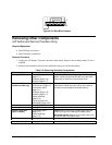
Reassembly Notes: Make sure the volume control is
oriented properly (pins facing inward). Insert the tabs
on the ends of the panel into the slots in the bottom
case.
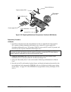
Panel, mini-PCI
Plug-in module (page 2-5).
Hard disk drive (page 2-7).
Power button panel
(page 2-11).
Keyboard (page 2-15).
Heatsink (page 2-17).
Display assembly
(page 2-13).
Top case (page 2-20).
On the rear of the computer, remove the screw at the
far left end (nearest the mini-PCI panel).
Omnibook 6000: Detach the cables from mini-PCI
card and motherboard.
Omnibook 6100: Remove the motherboard (page
2-28), then detach the cables.
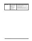
Panel, vent (Omnibook
6000 models only)
Plug-in module (page 2-5).
Hard disk drive (page 2-7).
Power button panel
(page 2-11).
Keyboard (page 2-15).
Heatsink (page 2-17).
Display assembly
(page 2-13).
Top case (page 2-20).
Reassembly Notes: Insert the pin on the back end of
the panel under the bracket on the bottom case, and
the tabs on the ends of the cover into the slots in the
bottom case.