


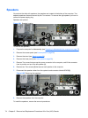
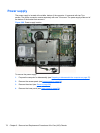
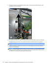
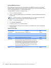
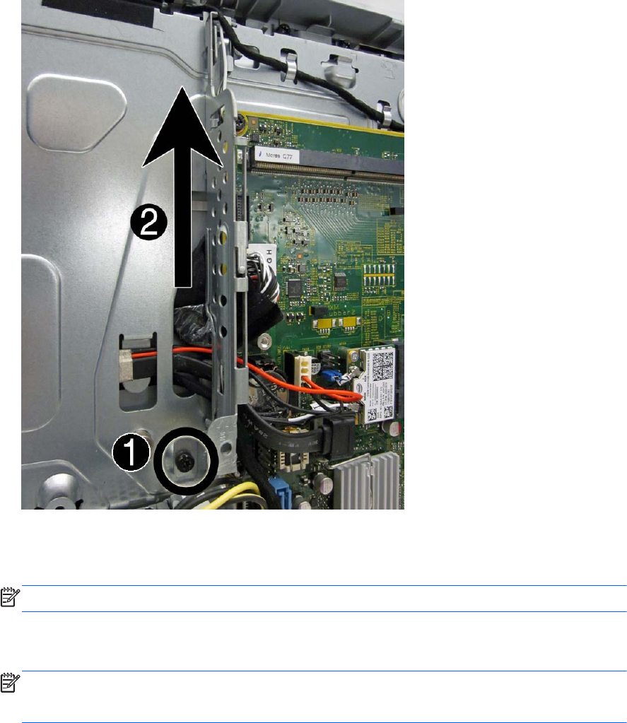
11. Remove the cable mounting bracket by removing the Torx screw (1), and then sliding it up (2)
and lifting it out of the computer.
Figure 6-70 Removing the cable mounting bracket
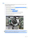
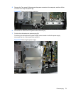
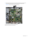
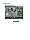
12. On model 6300, remove the eight Torx screws (1) that secure the system board to the computer.
On model 8300, remove the ten Torx screws that secure the system board to the computer.
NOTE: Model 6300 shown in the following image.
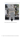
13. Position the cables on the left side of the board out of the way (2) so you can freely slide the
board out of the computer.
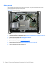
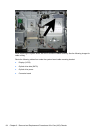
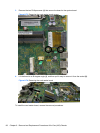
NOTE: To allow the system board to slide up so you can remove it, you must place the cables
in the cable retention areas built into the chassis to the left of the system board. Failure to move
the cables out of the way will impede system board removal.
82 Chapter 6 Removal and Replacement Procedures All-in One (AIO) Chassis