


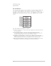

q Page Map Register: This read/write register defines the internal location of the
movable window into the device’s DSP bus. (This 512 kB window begins at 512
kB into the device’s A24 registers.) The eight least significant bits of the Page
Map register are the page number. These bits are mapped to the internal DSP
bus address lines as follows:
Bit 0: DSP A(17)
Bit 1: DSP A(18)
Bit 2: DSP A(19)
Bit 3: DSP A(20)
Bit 4: DSP A(21)
Bit 5: DSP A(22)
Bit 6: DSP A(30) and A(24)
Bit 7: DSP A(31)
The eight most significant bits of the Page Map Register are always zero (0).
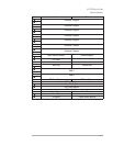
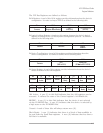
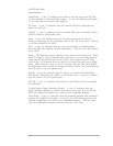
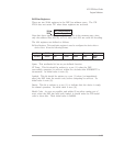
q IRQ Config Register: This register configures the first VME Bus interrupt source.
It provides for selection of the VME Bus IRQ level used, and a bit mask. It has
the following format:
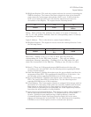
Bit 15-8 7-4 3 2-0
Contents Mask Unused
IRQ
Enabled
IRQ
Line
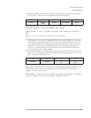
Mask: This is a bit mask used to enable up to eight interrupt causes. A
bit value of zero (0) disables the corresponding interrupt source. RESET
VALUE: 0
IRQ Enable: A one (1) in this bit enables the generation of IRQ’s. A zero
(0) resets each of the eight interrupt causes and status bits. RESET
VALUE: 0
IRQ Line: This field select which VME Bus IRQ line is driven by this
device. A value of zero (0) disconnect the interrupt source. RESET
VALUE: 0
HP E1432A User's Guide
Register Definitions
A-8