


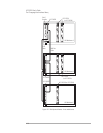
In the BOOTING state, the digital processors of the module load their
parameters, and their program. Once done, the module releases the
Sync/Trigger line and moves to the BOOTED state. The HP E1432A stays
in the BOOTED state until it sees a high-to-low transition of the
Sync/Trigger line (that is, all the HP E1432As in the system have booted).
In the SETTLING state, the digital filters are synchronized, and the digital
filter output is ‘settled’ (it waits N samples before outputting any data).
Once the module is settled, it advances to the PRE_ARM state.
In the PRE_ARM state, the module waits for a pre-arm condition to take
place. The default is to auto-arm, so the module would not wait at all in
this case. When the pre-arm condition is met, the module releases the
Sync/Trigger line and advances to the IDLE state.
This complete measurement sequence initialization, from TESTED through
BOOTING, BOOTED, SETTLING, PRE-ARM, and IDLE, can be performed
with a call to the function e1432_init_measure.
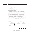
Measurement Loop
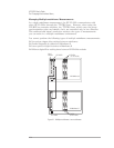
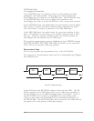
This section describes the measurement loop in the HP E1432A.
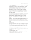
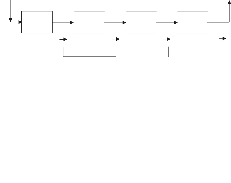
The progression of measurement states and the corresponding Sync/Trigger
line transitions are:
In the IDLE state the HP E1432A writes no data into the FIFO. The HP
E1432A remains in the IDLE state until it sees a high-to-low transition of
the Sync/Trigger line or an RPM arm/trigger point is calculated. If any of
the HP E1432As in the system is programmed for auto arming (with
e1432_set_auto_arm), the Sync/Trigger line is immediately pulled low by
that HP E1432A. The HP E1432A may also be moved to the ARM state by
an explicit call to the function e1432_arm_measure.
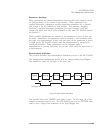
Arm Trigger MeasureIdle
LH
L
HL H
L
H
Sync/Trigger line
Figure 4-5: Measurement loop
HP E1432A User's Guide
The C-Language Host Interface Library
4-20