


Synchronization in Multiple-mainframe Measurements
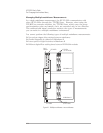
A TTL Trigger line between HP E1432As making group measurements
keeps all modules synchronized. This is an open-collector line where each
module holds the one designated as the SYNC line low until the module is
ready to advance to the next measurement state. Another TTL Trigger line
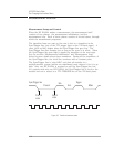
is designated to carry the sample clock to all modules. This shared sample
clock may come from any HP E1432A module in Mainframe A or from an
external signal routed through the Slot 0 Commander in Mainframe A.
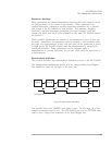
One module is responsible for pulling the SYNC line low to start each
group’s state transition. Then, each module holds the line low until it is
ready. When all modules are ready, the SYNC line drifts high. The
unidirectional line prevents modules in Mainframe B from holding-off
modules in Mainframe A.
The lowest logical address must be in Mainframe A because of VXI-MXI and
Resource Manager (RM) constraints. Group constraints with the C-Library
force modules in Mainframe A to have their FIFOs emptied last. The
C-Library reads data in channel order, so the highest channel is read last.
To get this to work automatically, the call to e1432_assign_channels() must
list the logical addresses in descending order.
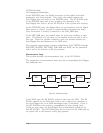
Channel triggering must be done only by modules in Mainframe A. A
trigger in any other mainframe would not be communicated back on the
SYNC line to Mainframe A. The C-Library itself selects the HP E1432A
with the highest channel number for synchronization.
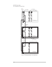
VXI-MXI Module Setup and System Configuration
To set up your multiple mainframe system, follow the “Hardware Installation
Rules” which appear in Chapter 2 of the HP E1482B VXI-MXI Bus Extender
User’s Manual. This allows the Resource Manager to configure your system.
The VXI-MXI Module setup in Mainframe A needs to be changed from those
set by the factory. The VXI-MXI module is not the Slot 0 Controller for
Mainframe A. See Table 2-1. Configuration Settings in the HP E1482B
VXI-MXI Bus Extender User’s Manual. This requires changing several
switch settings.
q Set the module as not being the Slot 0 Controller.
q Set the VME timeout to 200 µs.
q Set the VME BTO chain position to 1 extender, non-slot0.
q Do not source CLK10.
q Set the proper logical address.
HP E1432A User's Guide
The C-Language Host Interface Library
4-17