


Module Features
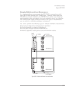
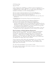
Data Flow Diagram and FIFO Architecture
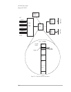
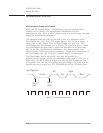
The illustration on the next page shows data flow in the HP E1432A. In
this example there are four 4-channel input assemblies for a total of 16
input channels. The data for all channels is sent to the FIFO. The FIFO is
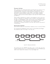
divided into sections, one for each channel. The data moves through a
circular buffer (first-in-first-out) until a trigger causes it to be sent on to
the VME Bus. The data can also be sent to the Local Bus if option UGH is
present.
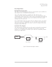
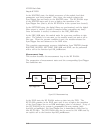
The size of the sections in the FIFO is flexible. The amount of DRAM
memory for each channel is the total DRAM memory divided by the number
of channels. The standard DRAM size is 4 MB; an optional 32 MB DRAM is
available.
The trigger can be programmed to trigger on the input or on information
from the software. The following are examples of ways a trigger can be
generated.
q input level or bound
q source
q external trigger
q RPM level (with tachometer option AYE)
q ttl_trigger (VXI backplane)
q freerun (automatic)
HP E1432A User's Guide
Using the HP E1432A
3-15