


Installing and Configuring the HP E1459A 15
Caution The user MUST ensure, based upon the programmed debounce
period and internal delays, that data to be captured has
propagated the debouncers and is fully setup prior to the
assertion of the externally generated capture clock.
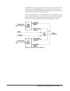
The module has two primary modes of operation: the module can interrupt
your software when an event occurs or your software can periodically poll
the module to determine if an event has occurred. If the channel data
registers are serviced via a "polled mode" method (which is not keyed to the
posting of the "marker bits" or the occurrence of an interrupt), no timing
relationship will necessarily exist with the debounced event. As a result, a
small window of uncertainty exists between input latch timing and debounce
circuit timing.
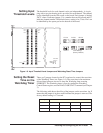
Input Edge
Detection
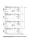
Each channel may be programmed to sense the occurrence of a qualified
edge transition of either polarity, or both concurrently. All channels are
preprocessed via the debounce circuits before presentation to the edge detect
logic. Edge detection is performed (by sampling methods) within each of the
four ports, in groups of 16 channels per port. If enabled, each port will post
an "Edge Interrupt Marker" to the control logic circuitry on the occurrence
of a qualified edge event for any active channel within its channel group.
(The static state of these markers may be tested via the "Edge Interrupt
Status Register." These markers are also accessible at the front panel.)
Caution Edge Detect Markers are cleared by a read of the register
causing the marker to be posted. Since there is no high-level
method of determining whether a positive or negative edge
event is generating the marker, both edge detect registers
(positive and negative) within a channel group, MUST be read
during the service interval to identify ALL edge events which
may have potentially occurred.
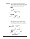
Each marker bit is forced inactive for a two clock (16 MHz) periods each
time either edge detect register is read. (The edge detect register is then
cleared at the end of the cycle.) If the register that is not being read is inactive
and remains inactive, the marker will continue to remain inactive. If the
register that is not read is active or becomes active, the marker is again
posted to the "control" logic. The control logic detects this event and stores
this occurrence in a flip-flop which marks the pending need for service. If
this marking register, (now active), is then read and ultimately cleared, the
marker will become inactive and will remain inactive until the subsequent
occurrence of another qualified edge event. The control logic detects this
"cleared marker condition" and consequently clears the pending service
request flip-flop.
External edge events which occur concurrently with a register read/clear
cycle are queued and post-processed on completion of the cycle.