


22 Installing and Configuring the HP E1459A
Connecting User
Inputs
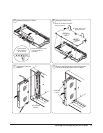
The HP E1459A Isolated Digital Input/Interrupt module consists of a
component module and a terminal block. User inputs for each channel
consists of a low and a high connection for each channel. The inputs will
only detect signals of a positive polarity. A logical "1" will only be detected
if the high terminal is at a higher potential than the low terminal. It must also
meet the drive requirements for the voltage threshold selected.
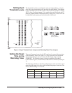
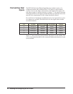
For each block of 16 channels an additional active low input and two active
low outputs are available. The table below lists the signal names and the
associated channels.
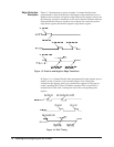
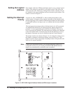
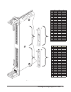
Figure 1-7 shows the front panel terminals and pinouts for the module. The
cover to the terminal module is silk-screened to indicate the function of each
screw terminal.
Port Channels External Trigger Data Available Interrupt
0 0 through 15 XTRIG0N DAV0N INTR0N
1 16 through 31 XTRIG1N DAV1N INTR1N
2 32 through 47 XTRIG2N DAV2N INTR2N
3 48 through 63 XTRIG3N DAV3N INTR3N