


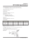


76 HP E1459A Register Definitions
Addressing the Registers
To read or write to specific registers you must address a particular register
within a module. The registers within a module are located using a fixed
offset. The module address is based upon the module's logical address.
There are two basic ways of accessing registers. One method uses the logical
address directly to access a particular card using VXI:READ and
VXI:WRITE commands through a command module. The other method can
be used with an embedded controller that locates A16 data space within its
memory map. The memory mapping allows registers to be directly read or
written with moves to/from memory.
The factory setting of the logical address dip switch is 144 (90 hex). This
value is used in the following examples.
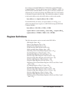
Register Access
with Logical
Address
When using the HP E1406 Command Module to access registers via
VXI:READ and VXI:WRITE commands, the logical address is used to
determine which VXI module is being accessed.
Note Refer to the HP E1406 Command Module documentation for usage of the
VXI:READ and VXI:WRITE commands and other related commands.
The following commands are sent to the HP E1406 Command Module via
the HP-IB. The following example shows a portion of an HP BASIC
program. The controller could either be external or embedded in the VXI
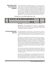
Mainframe. This example shows the Status/Control Register being
accessed.
! Writes FFFF hex to Control Register
OUTPUT 70900;"VXI:WRITE 144,4,#HFFFF"
! Reads from Status Register
OUTPUT 70900;"VXI:READ? 144,4"
ENTER 70900;Status
Register Access
with Memory
Mapping
When using an embedded controller VXI A16 address space is usually
mapped to some block of memory within the controllers addressable
memory space.
Note Refer to your embedded controller manual to determine where VXI A16 is
mapped. There may be other methods of accessing the VXI backplane.
What is shown here is the method in which A16 addresses are calculated
for a module.