


20 Installing and Configuring the HP E1459A
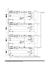
Setting the Logical
Address
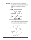
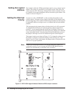
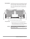
Each module within the VXIbus mainframe must be set to a unique logical
address. The setting is controlled by an 8 pin dip switch. This allows for
values from 0 to 255. The factory setting of this switch is decimal 144. No
two modules in the same mainframe can have the same logical address. The
location is shown in Figure 1-5.
Setting the Interrupt
Priority
At power on, after a SYSRESET, or after resetting the module via the
control register, all masks will be cleared, interrupts will be disabled, and
internal triggering will be enabled. With interrupts enabled, an interrupt will
be generated whenever an edge occurs on a channel that has been enabled
properly.
The interrupt priority jumper selects which priority level will be asserted.
As shipped from the factory, the interrupt priority jumper should be in
position 1. In most applications this should not be changed. When set to
level X interrupts are disabled. The interrupt priority jumpers are identified
on the sheet metal shield. A hole has been cut into the shield for access to
the jumpers. Interrupts can also be disabled using the Control Register.
The jumper locations are shown in Figure 1-5. To change the setting, move
the jumper or jumpers to the desired setting. If the card uses two 2-pin
jumpers versus a single 4 pin jumper, the jumpers must all be placed in the
same row for proper operation.
Note Consult your mainframe manual to be sure that backplane jumpers are
configured correctly. If you are using the HP E1401B Mainframe these
jumpers are automatically set when the card is installed.
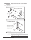
Figure 1-5. HP E1459A Logical Address Switch and IRQ Jumper Locations