


HP E1459A Register Definitions 75
Appendix B
HP E1459A Register Definitions
Overview
The HP E1459A Isolated Digital Input/Interrupt module is a register-based
slave device. There are 64 isolated inputs which can be used for detecting
rising and/or falling edges independently. Each 16 channels has a set of
registers used to define the detection of interrupt conditions. Listed below
are the different register types on this module.
• ID Register - Identifies Hewlett-Packard as the manufacturer, and that
the card is an A16 register based device.
• Device Type Register - Identifies card as a HP E1459A.
• Status/Control Register - When read it returns device specific status
information. When written it to, it sets control bits. Bit 4 specifies the
registers for the upper or lower 32 channels.
• Edge Interrupt Status Register - This register indicates which Port
has detected an edge interrupt.
• Data Available Status Register (DAV) - This register indicates which
register has been externally triggered and has data available.
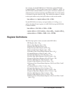
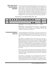
• Watchdog Timer Control/Status Register - The watchdog timer on
the module is enabled and pet using this register.
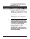
• Command Register - There are two of these registers, each controls
two ports; used to control triggering and enabling interrupts.
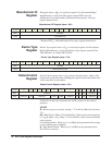
• Channel Data Register - There are four of these registers, one for
each port; these registers contain the current channel data.
• Positive Edge Detect Register - There are four of these registers, one
for each port; used to capture transitions from low to high levels.
• Negative Edge Detect Register - There are four of these registers, one
for each port; used to capture transitions from high to low levels.
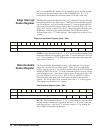
• Positive Mask Register - There are four of these registers, one for
each port; these registers enable data to be captured in the Positive
Edge Detect Registers.
• Negative Mask Register - There are four of these registers, one for
each port; these registers enable data to be captured in the Negative
Edge Detect Registers.
• Debounce Clock Register - There are two of these registers, one for
the lower two ports and one for the upper two ports. These registers
control the clock speed of the debouncers.