


Installing and Configuring the HP E1459A 25
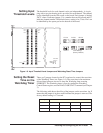
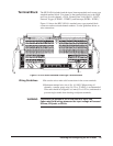
Terminal Block The HP E1459A includes both the input / interrupt module and a screw-type
standard terminal block. User inputs to the terminal block are to the High
and Low for each channel, +5Volt, Ground, Data Valid (DAV0 - DAV3),
External Trigger (XTRIG0 - XTRIG3), and Interrupt (INTR0 - INTR3) .
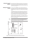
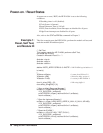
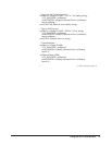
Figure 1-9 shows the HP E1459A’s standard screw-type terminal block
connectors and associated channel numbers. Use the guidelines below to
wire connections.
Figure 1-9. HP E1459A Standard Screw-type Terminal Block
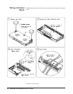
Wiring Guidelines • Be sure the wires make solid connections in the screw terminals.
• Maximum terminal wire size is No. 16 AWG. When wiring all
channels, a smaller gauge wire (No. 20 or 22 AWG) is recommended.
Wire ends should be stripped 5 to 6 mm (0.2 to 0.25 in.) and tinned to
prevent single strands from shorting to adjacent terminals.
WARNING To prevent the spread of fire in the case of a fault, use
flame-rated field wiring whenever the input voltage will exceed
30Vrms, 42Vpeak, or 60Vdc.
CH0 CH5
CH1
CH2
CH3
CH4
CH6
CH7
CH8
CH9
CH10
CH11
CH12
CH13
CH14
CH15
CH16
CH17
CH18
CH19
CH20
CH21
CH22
CH23
CH24
CH25
CH26
CH27
CH28
+5 GND
CH29
CH30
CH31
CH32
CH33
CH34
+5 GND
+5 GND
+5 GND
CH35
CH36
CH37
CH38
CH39
CH40
CH41
CH42
CH43
CH44
CH45
CH46
CH47
CH48
CH49
CH50
CH51
CH52
CH53
CH54
CH55
CH56
CH57
CH58
CH59
CH60
CH61
CH62
CH63
+5 GND
+5 GND
GNDDAVINTREXT
GNDDAV INTREXT
GNDDAVINTREXT
NotUsed