


HP E1459A Register Definitions 79
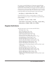
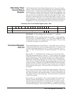
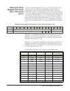
READ
E IRQ = When "1" it indicates that an INTRX line has transitioned from
being asserted.
D IRQ = When "1" it indicates that a DAVX line had been asserted.
M = MODID bit = "0" module has been selected.
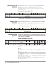
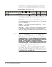
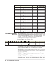
Bit 0 is the reset bit. Writing a "1" will force the card into reset. It must be
written back to "0" for normal operation of the card. The state of this bit is
returned on a read of this register.
Bit 4 is used to control which set of port registers are being accessed. Due to
the number of registers on this card, it is necessary to switch between
registers. This bit when set to "0" allows access to Port 0 and Port 1 data in
registers 10
h
through 2E
h
. This corresponds to the first 32 channels. When
this bit is a "1". Port 2 and Port 3 can be accessed in these same register
locations. The state of this bit is returned on a read of this register.
Bit 5 controls if edge interrupts are enabled ("1") or not ("0"). If enabled an
edge interrupt will generate an IRQ if other registers are properly enabled.
At least one port must have the Edge Enable bit set in the command register,
and have at least one bit enabled in one of the mask registers. If an edge
event occurs, IRQ will be asserted. This can be verified by reading the Edge
Interrupt Status Register to assure none are asserted. If any are asserted the
Edge Detect Register holding the edge event must be cleared. The state of
this bit is returned on a read of this register.
Bit 6 controls if IRQ will be asserted when data becomes available due to an
external trigger on any of the ports. A "1" enables the IRQ and a "0" disables
it. The interrupt will only occur if the following is true: The command
register for at least one of the ports must have the data ready enable bit set
in order to generate an interrupt. This can be verified by reading the Data
Available Status Register to assure that none are asserted. If any are asserted,
the data available indication will be cleared by reading any of the registers
associated with the port. The state of this bit is returned on a read of this
register.
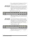
Bit 8 is a read only bit. When bit 5 is enabled, edge interrupts are enabled. It
indicates if an edge interrupt has occurred on any of the ports since the last
time IRQ was asserted. During the IACK cycle this bit will also appear as
bit 8 of the IACK response. It will then be reset. If bit 5 is not enabled this
bit can be polled to detect an edge event on any register. All pending edge
events must be cleared (read) before this bit can be reasserted.
Bit 9 is a read only bit. When bit 6 is enabled, data available interrupts are
enabled. It indicates if an external trigger has occurred on any of the ports
since the last time IRQ was asserted. During the IACK cycle this bit will also
appear as bit 9 of the IACK response. It will then be reset. If bit 6 is not
enabled this bit can be polled to detect an external trigger on any port. All
pending data available must be cleared (read) before this bit is reasserted.
Note In applications requiring interrupts, a commander will have to be assigned
as the interrupt handler of this module