


HP E1459A Register Definitions 87
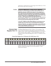
should only be enabled when in external trigger mode. When set to "0" the
DAV1/3 line cannot cause an interrupt.
Caution A potential hazard exists if software were to improperly
program the HP E1459A to post data-capture IRQ's with the
internally selected 1.0 MHz clock source. In this situation, a
DAV interrupt would be posted each microsecond (if software
were able to service at that rate), and would cause software to
continuously vector to interrupt service upon each "return from
service." Therefore, the HP E1459A should never be
programmed to generate DAV interrupts with the internal clock
source selected. (If bit 1 of the Command Register Word is set
to a one, then bit 2 must always be set to zero.)
In the HP E1459A the Data Ready Marker is guaranteed to be
cleared when the clock source is switched from internal to
external. Therefore, any capture clock which occurs within the
internal/external clock selection interval will not post a marker
to the control FPGA and will be lost.
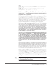
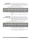
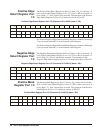
Channel Data
Register Port 1/3
The Channel Data Register for Port 1/3 (base + 22
h
) is read only. This
register returns the current (last) data that has been clocked into the data
capture circuitry. If bit 4 of the Control/Status Register is low ("0"), Port 1
data is accessed. If bit 4 is high ("1"), Port 3 data will be accessed. The
operation of these Channel Data Registers for Port 1/3 is identical to those
of Port 0/2.
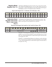
Channel Data Register Port 1/3 (Channels 16-31/48-63) (base + 22h)
Channels 16 through 31 are accessed when BS = 0 in the Status/Control
Register. Channels 48 through 63 are accessed when BS = 1 in the
Status/Control Register.
b + 22
h
15 14 13 12 11 10 9 8 7 6 5 4 3 2 1 0
Write No Effect
Read Ch31 Ch30 Ch29 Ch28 Ch27 Ch26 Ch25 Ch24 Ch23 Ch22 Ch21 Ch20 Ch19 Ch18 Ch17 Ch16
Read Ch63 Ch62 Ch61 Ch60 Ch59 Ch58 Ch57 Ch56 Ch55 Ch54 Ch53 Ch52 Ch51 Ch50 Ch49 Ch48