


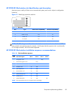
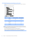
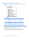
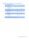
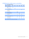

HP Z220 SFF Workstation slot identification and description
Maximum power used by all slots must not exceed total system power and is subject to configuration
limitations.
Figure 3-1 Identifying expansion card slots
Table 3-1 PCI slots
Slot Type Mechanical compatibility Electrical compatibility
1 PCIe2 x1 x1 x1
2 PCIe2 x16 (4) x16 x4
3PCIe3 x16 x16 x16
4 PCI 32/33 PCI PCI
NOTE: The PCIe designators indicate the mechanical connector size and number of electrical PCIe
lanes routed to an expansion slot. For example, x16 (8) means that the expansion slot is mechanically
a x16 length connector, with 8 PCIe lanes supported.
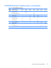
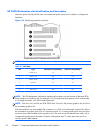
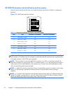
HP Z220 SFF Workstation installation sequence recommendations
Table 3-2 Slot Installation sequence
Load
order
Card description Slot 1 Slot 2 Slot 3 Slot 4
1 PCIe graphic card Only
2 Second PCIe graphic card Only
3 PCIe audio card 1st 2nd
4PCIe NIC card 1st 2nd
5 PCIe 1394a card 1st 2nd
6 PCIe Wireless card 1st 2nd
7 Second serial port kit 1st 2nd
8 Parallel port kit 1st 2nd
9 eSATA bulkhead kit 1st 2nd 3rd
NOTE: Slot sequenced from the rear I/O aperture to the board edge.
Component replacement guidelines
85