


HP Surestore FC 1Gb/2Gb Switch 16B Installation and Reference Guide 3-7
Operating the HP Surestore FC 1Gb/2Gb Switch 16B
3
Field-Replaceable Units (FRUs)
The power supplies, fan trays, and the entire switch can all be replaced in the field, without the use
of special tools. The switch can continue operating during the replacement of a fan tray or power
supply, if they are replaced one at a time. To simplify replacement, the switch has a minimum of
internal cables and no jumpers or hardware settings. Replacement instructions are provided with all
replacement units ordered.
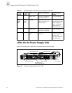
The right and left power supplies are identical and fit into either power supply slot. Once they are
installed, they are identified by the Fabric OS as power supply #1, which is on the right when
viewing the switch from the power supply side, and power supply #2, on the left (see Figure 3-2 on
page 3-4). The right and left fan trays are also identical and fit into either fan tray slot. Each fan tray
contains two fans: the fans in the fan tray on the right when viewing the switch from the power
supply side are identified by the Fabric OS as fans #1 and #2, and the fans in the fan tray on the left
are identified as fans #3 and #4 (see Figure 3-2 on page 3-4).
Warning
This switch may have more than one power cable. To reduce the risk of
electric shock, disconnect both power cables before servicing.