


A-6 HP Surestore FC 1Gb/2Gb Switch 16B Installation and Reference
Product Specifications
A
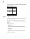
The port requires a straight serial cable with a female 9-pin subminiature-D connector. Only pins 2,
3, and 5 are supported; if pin 7 is used, the signal must always be driven high, using the pinouts
listed in the following table.
POST Specifications
The switch automatically performs POST when the switch is turned on, rebooted, or the system is
reset. POST includes a number of diagnostic tests: the success/fail test results can be monitored
through the LED activity, the error log, or command-line interface.
POST completes in 60 seconds. A slightly longer version of the memory portion of the test is
performed after cold boots. A cold boot occurs after a complete power cycle, when the switch is
turned off then on. A warm boot is any other type of boot, such as an operating system reboot or
switch panic.
POST includes the following steps:
1. Preliminary POST diagnostics are run.
2. Operating system is initialized.
3. Hardware is initialized.
4. Diagnostic tests are run on a number of functions, including internal connections and circuitry,
port functionality, ability to send and receive frames, ability to implement QuickLoop
functionality, all aspects of memory, parity, statistics counters, and correct serialization.
5. Universal Port configuration is performed.
6. Links are initialized.
7. Fabric is analyzed. If ports are connected to other fabric elements, the principal switch in the
fabric is identified.
8. Port addresses are assigned. The switch attempts to retain any previously assigned port
addresses.
9. Unicast routing tables are constructed.
10. Normal port operation is enabled.
Table A-5 Cabling Pinouts if Pin 7 is Used
PIN Signal Description
1
2 TxData Transmit Data
3 RxData Receive Data
4
5 GND Logic Ground
6
7 CTS Clear to Send
8
9