


Introduction 11
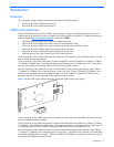
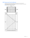
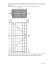
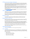
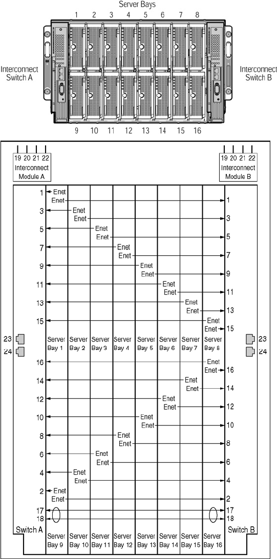
The following diagram illustrates the Ethernet signal connectivity between server bays and the interconnect bays
through the backplane for p-Class server enclosures with enhanced backplane components that support high-density
blade servers.
Figure 4 Ethernet signal connectivity for server enclosures with enhanced backplane components
The interconnect switch does not affect or determine NIC enumeration and the associated mapping of NIC interfaces
to interconnect switch ports. The numbering of the NICs on the server (for example, NIC 1, NIC 2, NIC 3) is
determined by the server type, the server operating system, and what NICs are enabled on the server.