


Introduction 18
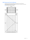
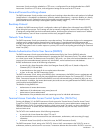
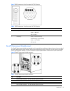
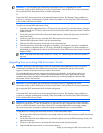
Figure 7 GbE2 Interconnect Switch front panel NIC LED functions
Table 3 GbE2 Interconnect Switch front panel NIC LED functions
Item LED Description Status
1 Link speed Amber = 1000 Mb/s
Green = 100 Mb/s
Off = 10 Mb/s
2 Link activity Green = Link and no activity
Green flashing = Link and activity
Amber = Port disabled
Off = No link
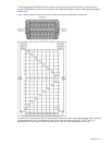
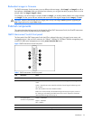
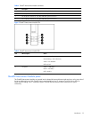
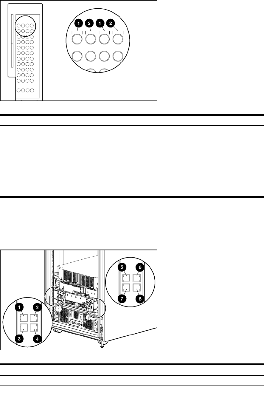
QuadT2 Interconnect Module panel
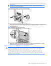
The QuadT2 Interconnect Modules are inserted into the bottom-left-most and bottom-right-most bays on the rear side of
the server blade enclosure. Each QuadT2 Interconnect Module has four RJ-45 connectors with link activity and speed
LEDs for uplink network cabling. Four RJ-45 connectors support Gigabit Ethernet connections for uplink connectivity.
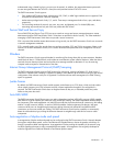
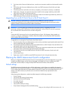
Figure 8 QuadT2 Interconnect Module connectors
Table 4 QuadT2 Interconnect Module connectors
Item Description
1 Port 22 RJ-45 connector for 10/100/1000 Mb uplink for Switch B
2 Port 21 RJ-45 connector for 10/100/1000 Mb uplink for Switch B
3 Port 20 RJ-45 connector for 10/100/1000 Mb uplink for Switch B
4 Port 19 RJ-45 connector for 10/100/1000 Mb uplink for Switch B