


Setting up and installing the GbE2 interconnect switch 23
IMPORTANT: If you are replacing an existing GbE2 Interconnect Switch, or upgrading from a GbE
Interconnect Switch, an RJ-45 Patch Panel, or an RJ-45 Patch Panel 2, and you have strict security requirements:
Do not cable the GbE2 Interconnect Switch until after configuration.
Or
Connect the GbE2 Interconnect Switch to the optional Diagnostic Station. The Diagnostic Station enables you
to power up, configure, and diagnose a ProLiant p-Class server blade or a ProLiant p-Class GbE2 Interconnect
Switch outside of the rack environment.
To replace an existing GbE2 Interconnect Switch:
1. If possible, save the configuration file to a TFTP server for later retrieval. For more information on saving a
configuration file to a TFTP server, refer to the HP ProLiant BL p-Class GbE2 Interconnect Switch Command
Reference Guide.
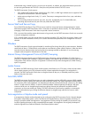
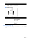
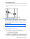
2. On the front side of the ProLiant BL p-Class server blade enclosure, release the ejector lever for the GbE2
Interconnect Switch.
3. Pull down on the ejector lever to unlock the GbE2 Interconnect Switch from the enclosure.
4. Slide the GbE2 Interconnect Switch out of the interconnect bay.
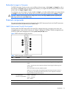
5. Slide the new GbE2 Interconnect Switch fully into the interconnect bay.
6. Close the ejector lever and let the switch boot up completely, so that network connectivity is established.
7. If you saved the configuration file to a TFTP server, download the configuration. For more information on
downloading a configuration file, refer to the HP ProLiant BL p-Class GbE2 Interconnect Switch Command
Reference Guide.
NOTE: Only replace the interconnect module if it is faulty, or if a different type of interconnect module is
required.
Upgrading from an existing GbE Interconnect Switch
CAUTION: Removing a GbE Interconnect Switch from a powered enclosure will result in the loss of network
communications between the server blade network ports that are connected through this switch and the
segment of network infrastructure those ports need to communicate.
For continued blade server network communication and services availability, do the following before you
remove the GbE Interconnect Switch. Redirect critical high-availability services or applications to use the
redundant network ports available on those blade servers that are connected through the redundant GbE
Interconnect Switch in the enclosure.
IMPORTANT: If you are replacing an existing GbE2 Interconnect Switch, or upgrading from a GbE
Interconnect Switch, an RJ-45 Patch Panel, or an RJ-45 Patch Panel 2, and you have strict security requirements:
Do not cable the GbE2 Interconnect Switch until after configuration.
Or
Connect the GbE2 Interconnect Switch to the optional Diagnostic Station. The Diagnostic Station enables you
to power up, configure, and diagnose a ProLiant p-Class server blade or a ProLiant p-Class GbE2 Interconnect
Switch outside of the rack environment.
IMPORTANT: By default, both the GbE Interconnect Switch and GbE2 Interconnect Switch have STP enabled
and have X-Connect ports (17 and 18) bundled in to a port trunk. During an upgrade from a GbE Interconnect
Switch to a GbE2 Interconnect Switch, there will be an STP convergence delay due to the topology change.
This causes a temporary interruption to packet forwarding on the attached Layer 2 switching network.
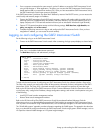
To upgrade from an existing GbE Interconnect Switch to a GbE2 Interconnect Switch:
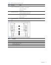
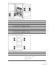
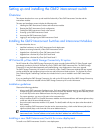
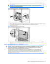
1. On the rear side of the ProLiant BL p-Class server blade enclosure, remove the interconnect module from the top-
left module bay.
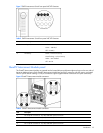
2. On the front side of the server blade enclosure, release the ejector lever for the GbE Interconnect Switch in the
right interconnect bay.
3. Pull down on the ejector lever to unlock the GbE Interconnect Switch from the enclosure.
4. Slide the GbE Interconnect Switch out of the interconnect bay.