


Setting up and installing the GbE2 interconnect switch 27
To connect the interconnect modules to the network:
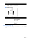
1. Connect your network cables to the interconnect modules. For connector locations, refer to the “QuadT2
Interconnect Module panel” section or “QuadSX Interconnect Module panel” section in the “Introduction”
chapter.
2. Gather your network cables for the right side of the rack.
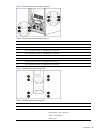
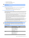
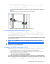
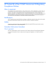
3. Insert the end of the cable-retaining bracket (provided with the bus bar and power bus boxes) into the cable
bracket (1).
4. Tighten the thumbscrew to secure the cable retaining bracket over the cables (2).
Figure 14 Installing the cable-retaining bracket
5. Repeat steps 2 through 4 for the network cables on the left side of the rack.
Powering up the GbE2 Interconnect Switch
If the server blade enclosure has power applied, the GbE2 Interconnect Switch automatically begins to power up
when installed. The power status LED on the front of the GbE2 Interconnect Switch starts out as amber to indicate that
power is connected to the GbE2 Interconnect Switch. After 30 seconds, the power status LED turns to green to
indicate that the GbE2 Interconnect Switch is powered up. After the built in self-test flashes all LEDs, the active links
are illuminated, and the power status LED stays green.
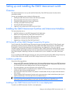
You can manually force the GbE2 Interconnect Switch to power up by pressing the Pwr/Rst button through the access
hole in the front panel of the GbE2 Interconnect Switch while the power status LED is amber. HP recommends using a
small blunt object for this purpose.
CAUTION: Pressing the Pwr/Rst button while the power status LED is green will reset the GbE2 Interconnect
Switch.
IMPORTANT: If the server blade enclosure does not have power applied, refer to the system setup and
installation guide for the server blade enclosure.
Accessing the GbE2 Interconnect Switch
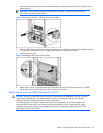
The GbE2 Interconnect Switch can be accessed using the serial (DB-9) management port or an Ethernet connection.
• To access the GbE2 Interconnect Switch locally, use the front panel serial management port.
• To access the GbE2 Interconnect Switch through an Ethernet connection, use either the GbE2 Interconnect
Switch front panel RJ-45 ports or one of the following:
• The uplink RJ-45 ports in the QuadT2 Interconnect Module
• The uplink LC fiber ports in the QuadSX Interconnect Module
To access the GbE2 Interconnect Switch via an Ethernet connection, you need to assign it an IP address. By default,
the GbE2 Interconnect Switch is set up to obtain its IP address from a BOOTP server existing on the attached network.
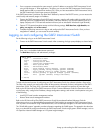
1. Access the BOOTP server and use the GbE2 Interconnect Switch MAC address to obtain the switch IP address.
The MAC address is printed on the MAC address label attached to the GbE2 Interconnect Switch.