


Technical Reference Guide www.hp.com 4-13
System Support
4.5.4 Thermal Sensing and Cooling
All systems feature a variable-speed fan mounted as part of the processor heatsink assembly. All
systems also provide or support an auxiliary chassis fan. All fans are controlled through
temperature sensing logic on the system board and/or in the power supply. There are some
electrical differences between form factors and between some models, although the overall
functionality is the same. Typical cooling conditions include the following:
1. Normal—Low fan speed.
2. Hot processor—ASIC directs Speed Control logic to increase speed of fan(s).
3. Hot power supply—Power supply increases speed of fan(s).
4. Sleep state—Fan(s) turned off. Hot processor or power supply will result in starting fan(s).
The RPM (speed) of all fans is the result of the temperature of the CPU as sensed by speed
control circuitry. The fans are controlled to run at the slowest (quietest) speed that will maintain
proper cooling.
✎
Units using chassis and CPU fans must have both fans connected to their corresponding headers
to ensure proper cooling of the system.
4.6 Register Map and Miscellaneous Functions
This section contains the system I/O map and information on general-purpose functions of the
PCH and I/O controller.
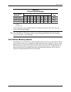
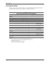
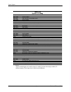
4.6.1 System I/O Map
Table 4-9 lists the fixed addresses of the input/output (I/O) ports for a system booting 16-bit
legacy OS..