


6-6 www.hp.com Technical Reference Guide
Integrated Graphics Subsystem
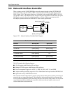
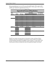
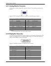
6.4.1 Analog Monitor Connector
All form factors include a legacyVGA connector (Figure 6-2) for attaching an analog video
monitor:
Figure 6-2. DB-15 Analog VGA Monitor Connector, (as viewed from rear of chassis).
NOTE:
[1] Fuse automatically resets when excessive load is removed.
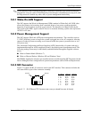
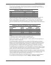
6.4.2 DisplayPort Connector
All systems include a DisplayPort connector (Figure 6-3) for attaching a digital monitor. This
interface also supports the use of an optional adapter/dongle for converting the DisplayPort
output to a DVI, HDMI, or analog VGA output.
Figure 6-3. DisplayPort Connector, (as viewed from rear of chassis).
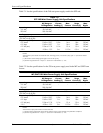
Table 6-4. DB-15 Monitor Connector Pinout
Pin Signal Description Pin Signal Description
1 R Red Analog 9 PWR +5 VDC (fused) [1]
2 G Blue Analog 10 GND Ground
3 B Green Analog 11 NC Not Connected
4 NC Not Connected 12 SDA DDC Data
5 GND Ground 13 HSync Horizontal Sync
6 R GND Red Analog Ground 14 VSync Vertical Sync
7 G GND Blue Analog Ground 15 SCL DDC Clock
8 B GND Green Analog Ground -- -- --
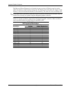
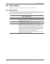
Table 6-5. DB-15 Monitor Connector Pinout
Pin Signal Pin Signal
1 ML Lane (p) 0 11 Ground
2 Ground 12 ML Lane (n) 3
3 ML Lane (n) 0 13 Ground
4 ML Lane (p) 1 14 Ground
5Ground 15AUX Ch (p)
6 ML Lane (n) 1 16 Ground
7 ML Lane (p) 2 17 AUX Ch (n)
8 Ground 18 Hot Plug Detect
9 ML Lane (n) 2 19 DP Power Return
10 ML Lane (p) 3 20 DP Power