


Technical Reference Guide www.hp.com 7-9
Power and Signal Distribution
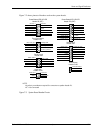
7.5 Signal Distribution
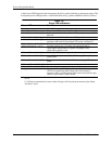
Table 7-7 lists the reference designators for LEDs, connectors, indicators, and switches used on
the system boards. Not all components will be present on all system boards.
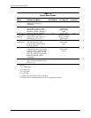
Table 7-7.
System Board Connector, Indicator, and Switch Designations
Designator Component function
CR1 +5 VDC LED
E1 Descriptor table override header
E14 SPI ROM boot block header
E49 / JP49 Password clear header / jumper
J9 Stacked RJ-45 & dual USB connectors
J10 Stacked quad USB connectors
J20 PCI 2.3 connector
J21 PCI 2.3 connector
J22 PCI 2.3 connector
J31 PCIe x1 connector
J32 PCIe x1 connector
J41 PCIe x16 graphics connector or MXM graphics slot
J42 PCIe x4 graphics (x16) connector
J50 Parallel port
J64 DisplayPort connector
J65 DVI connector
J66 Keyboard connector
J67 Mouse connector
J68 Stacked keyboard, mouse PS/2 connectors
J69 VGA monitor DB-15 connector
J70 Primary single USB
J71 Secondary single USB
J72 Microphone jack
J73 Line-In audio jack
J74 Line-out audio jack
J75 Headphone jack
J77 Double-stacked headphone/microphone audio jacks
J78 Double-stacked line-in, headphone/line-out audio jacks
J80 Stacked serial / audio
J81 Primary double USB
J82 Secondary double USB
J83 Triple-stacked audio
J103 DC input power
J105-107 PCIe Mini-Card
J151 Powered USB +12V
J152 Powered USB +24V
J200 Cash drawer connector
P1 Power supply header
P2 Power supply command/status header
P3 Power supply Vccp 12V header
P5 Control panel (power button, power LED) header