


5-10 www.hp.com Technical Reference Guide
Input/Output Interfaces
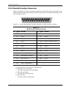
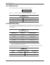
5.6.1 USB Connector
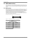
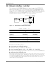
These systems provide type-A USB ports as shown in Figure 5-7.
Figure 5-7. Universal Serial Bus Connector (as viewed from rear of chassis)
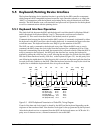
5.6.2 USB Cable Data
The recommended cable length between the host and the USB device should be no longer than
sixteen feet for full-channel (12 MB/s) operation, depending on cable specification (see
following table).
NOTE: For sub-channel (1.5 MB/s) operation and/or when using sub-standard cable shorter
lengths may be allowable and/or necessary.
The shield, chassis ground, and power ground should be tied together at the host end but left
unconnected at the device end to avoid ground loops.
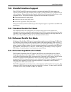
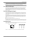
Table 5-6.
USB Connector Pinout
Pin Signal Description Pin Signal Description
1 Vcc +5 VDC 3 USB+ Data (plus)
2USB- Data (minus) 4GNDGround
1 2
3 4
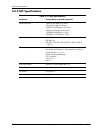
Table 5-7.
USB Cable Length Data
Conductor Size Resistance Maximum Length
20 AWG 0.036 16.4 ft (5.00 m)
22 AWG 0.057 9.94 ft (3.03 m)
24 AWG 0.091 6.82 ft (2.08 m)
26 AWG 0.145 4.30 ft (1.31 m)
28 AWG 0.232 2.66 ft (0.81 m)
Table 5-8.
USB Color Code
Signal Insulation color Signal Insulation Color
Data + Green Vcc Red
Data - White Ground Black