


Technical Reference Guide www.hp.com 5-15
Input/Output Interfaces
✎
For the features in the following paragraphs to function as described, the system unit must be
plugged into a live AC outlet. Controlling unit power through a switchable power strip will, with
the strip turned off, disable any wake, alert, or power management functionality.
5.8.1 Wake-On-LAN Support
The NIC supports the Wired-for-Management (WfM) standard of Wake-On-LAN (WOL) that
allows the system to be booted up from a powered-down or low-power condition upon the
detection of special packets received over a network. The detection of a Magic Packet by the
NIC results in the PME- signal on the PCI bus to be asserted, initiating system wake-up from an
ACPI S1 or S3 state.
5.8.2 Power Management Support
The NIC supports WOL and ACPI power management environments. The controller receives
3.3 VDC (auxiliary) power as long as the system is plugged into a live AC receptacle, allowing
support of wake-up events occurring over a network while the system is powered down or in a
low-power state.
The Advanced Configuration and Power Interface (ACPI) functionality of system wake up is
implemented through an ACPI-compliant OS and is the default power management mode. The
following wakeup events may be individually enabled/disabled through the supplied software
driver:
■ Wake on Pattern Match (Windows 7)
■ Wake on Directed Packets (Windows XP and Windows Vista)
The PROSet Application software (pre-installed and accessed through the NIC Properties (inside
Device Manager) allows configuration of operational parameters such as WOL and duplex mode.
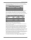
5.8.3 NIC Connector
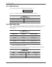
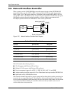
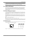
Figure 5-11 shows the RJ-45 connector used for the NIC interface. This connector includes the
two status LEDs as part of the connector assembly.
Figure 5-11. RJ-45 Ethernet TPE Connector and Pinout (as viewed from rear of chassis)
124 38
7
6
5
Pin Description
1 Transmit+
2 Transmit-
3 Receive+
6 Receive-
Activity LED
Speed LED
Pin
1
2
3
4
5
6
7
8
10Base T
TX+
TX-
RX+
nc
nc
RX-
nc
nc
100Base-TX
TX_D1+
TX_D1-
RX_D2+
BI_D3+
BI_D3-
RX_D2-
BI_D4+
BI_D4-
1000Base-T
BI_DA+
BI_DA-
BI_DB+
BI_DC+
BI_DC-
BI_DB-
BI_DD+
BI_DD-