


Technical Reference Guide www.hp.com 7-3
Power and Signal Distribution
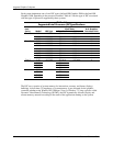
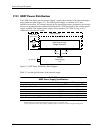
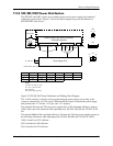
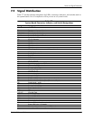
7.2.2 SFF /MT/CMT Power Dis tribu t ion
The SFF, MT, and CMT systems use a common power source power supply unit contained
within the system chassis. Figure 7-2 shows the block diagram for power distribution for
SFF/MT/CMT form factors.
NOTES:
Connectors not shown to scale.
All + and
– values are VDC.
Rsvd= Reserved
RTN = Return (signal ground)
Figure 7-2. SFF/MT/CMT Power Distribution and Cabling, Block Diagram
The +12Vsb (auxilary) voltage is always produced by the power supply unit as long as the
system is connected to a live AC source. When the PS On signal is asserted, the power supply
unit produces the +12 Vmain, +12 Vcpu, and -12 V outputs.
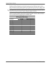
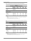
The standard 240-watt and 320-watt power supplies have a 70% minimum efficiency rating at
100% of the rated load, measured while operating from 100 VAC @60 Hz and 230 VAC @ 50
Hz.
The optional 80Plus Gold-rated high-efficiency 240-watt and 320-watt power supplies operate at
the following efficiencies while operating from 100 VAC @60 Hz and 230 VAC @ 50 Hz :
100% of rated load: 87% efficient
50% of rated load: 90% efficient
20% of rated load: 87% efficient
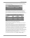
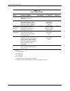
Conn Pin 1 Pin 2 Pin 3 Pin 4 Pin 5 Pin 6
P1 RTN RTN
–12 V +12 Vmain +12 Vmain +12 Vsb
P2 FANcmd Fan Speed PS On Pwr Good Rsvd Rsvd
P3 RTN RTN +12 Vcpu
+12 Vcpu
System Board
Power On
Power Control Logic, DC/DC Converter
Front Bezel
& Voltage Regulators
Fan
PS
+12 Vcpu
Power Button
Spd
+12 Vmain +12 Vsb
90 - 264 VAC
NOTE: Return (RTN or ground) not shown.
-12 V
P1
On
Pwr
Good
P2 P3
P3
1
2
3
4
1
2
3
4
P2
56
P1
6
1
3
4
Fan
Cmd
Power Supply Unit