


7-2 www.hp.com Technical Reference Guide
Power and Signal Distribution
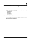
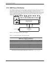
7.2.1 USDT Power Distribu tion
The USDT form factor uses an external (“brick”) supply that connects to the chassis through a
three-conductor cable (Figure 7-1). The USDT power supply is available in 135-watt
and180-watt versions. All voltages required by the processing circuits, peripherals, and storage
devices are produced on the system board from the 19.5 VDC produced by the external power
supply assembly. The external power supply always produces 19.5 VDC as long as it is
connected to an active AC outlet.
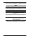
Figure 7-1. USDT Power Distribution, Block Diagram
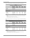
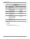
Table 7-1 lists the specifications of the external supply.
NOTES:
Total continuous power should not exceed power supply rating (i.e., 135 or180 watts).
[1] Using 100 VAC input. The output voltage is allowed to drop to a minimum of 15 VDC during the transient period.
Table 7-1.
USDT Power Supply Specifications
Parameter 135-watt supply 180-watt supply
Input Line Voltage Range 90–265 VAC 90–265 VAC
Line Frequency 47–63 Hz 47-63 Hz
Input Current, Maximum load @ 90 VAC 2.4 A 2.9 A
Output Voltage 19.5 VDC 19.5 VDC
Output Current, nominal load 3.5 A 4.6 A
Output Current, maximum load 6.9 A 9.2 A
Output Current, peak load (300 ms max) [1] 9.0 A 11 A
System Board
Power Supply
Power On
Power Control Logic,
Front Bezel
Voltage Regulators
Unit
Power Button
+19.5
USDT Chassis
90 - 264 VAC
Rtn
Pwr rating
& ID
VDC
External