


7-8 www.hp.com Technical Reference Guide
Power and Signal Distribution
NOTES:
Gn = Global state.
Sn = Sleep state.
Cn = ACPI state.
Dn = PCI state.
[1] Power cord is disconnected for this condition.
[2] Actual transition time dependent on OS and/or application software.
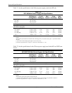
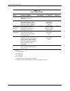
Table 7-6.
System Power States
Power
State System Condition
Power
Consumption
Transition
To S0 by [2]
OS Restart
Required
G0, S0, C0, D0 System fully on. OS and
application is running, all
components.
Maximum N/A No
G1, S1, C1, D1 System on, CPU is executing and
data is held in memory. Some
peripheral subsystems may be on
low power. Monitor is blanked.
Low < 2 sec after
keyboard or
pointing device
action
No
G1, S2/3, C2,
D2 (Standby/or
suspend)
System on, CPU not executing,
cache data lost. Memory is
holding data, display and I/O
subsystems on low power.
Low < 5 sec. after
keyboard, pointing
device, or power
button action
No
S4, D3
(Hibernation)
System off. CPU, memory, and
most subsystems shut down.
Memory image saved to disk for
recall on power up.
Low <25 sec. after
power button
action
Yes
G2, S5, D3
cold
System off. All components either
completely shut down or receiving
minimum power to perform system
wake-up. PCI and PCIe 3.3V slot
power (for wake-up events) can be
selectively disabled in BIOS
configuration.
Minimum <35 sec. after
power button
action
Yes
G3 System off (mechanical). No power
to any internal components except
RTC circuit. [1]
None — —