


7-10 www.hp.com Technical Reference Guide
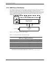
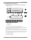
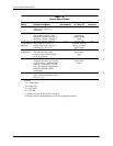
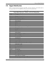
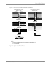
Power and Signal Distribution
✎
SATA power headers P160 and P161 are meant to provide power for internal SATA drives only.
The current limits for these connctors are:
6A/pin for CMT, MT, and SFF form factors
3A/pin for USDT the form facto
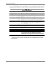
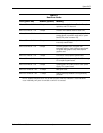
P6 Internal speaker header
P8 CPU fan header
P9 Chassis fan, primary, header
P10 Floppy drive header
P11 Power supply or rear chassis fan header
P20 Primary IDE header
P21 Secondary IDE header
P23 Front panel audio header
P24/P25 Front panel USB header
P52 Serial port, secondary, header
P53 Serial port, primary connector
P54 Serial port, primary header
P60 SATA0 (controller 1, primary master) connector (dark blue)
P61 SATA1 (controller 1, secondary master) connector (white)
P62 SATA2 (controller 1, primary slave) connector (light blue)
P63 SATA3 (controller 1, secondary slave) connector (orange)
P64 SATA4 / eSATA (controller 2, primary master) connector (black)
P124 Hood lock header
P125 Hood sense header
P126 Parallel port header
P128 Thermal sensor header
P150 Internal USB header
P151 Internal USB header
P160 SATA drive power (see note below)
P161 SATA drive power (see note below)
P165 Powered serial port LPC header
P200 Alternate system control panel header
SW1 Power button
SW50 Clear CMOS switch
XMM1 Memory slot (DIMM1 or SODIMM1)
XMM2 Memory slot (DIMM2 or SODIMM2)
XMM3 Memory slot (DIMM3 or SODIMM3)
XMM4 Memory slot (DIMM4 or SODIMM4)
XU1 Processor socket
XBT1 Battery socket
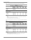
Table 7-7. (Continued)
System Board Connector, Indicator, and Switch Designations