


E-8
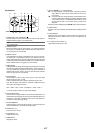
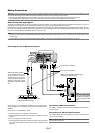
1. RGB1 IN / Component Input Connector (Mini D-Sub 15 Pin)
Connect your computer or other analog RGB equipment such as IBM
compatible or Macintosh computers. Use the supplied RGB cable to
connect to your computer. This also serves as a component input
connector that allows you to connect a component video output of
component equipment such as a DVD player. This connector also
supports SCART output signal. See page E-15 for more details.
RGB1 AUDIO Input Mini Jack (Stereo Mini)
This is where you connect the audio output from your computer or
DVD player when connected to the RGB1 input. A commercially avail-
able audio cable is required.
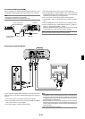
2. RGB2 IN / Component Input Connectors (BNC)
Connect R,G,B,H (Horizontal sync) and V (Vertical sync) outputs of
external equipment.
If using a component with a combined sync (SYNC) output, connect
it to the H/V terminal.
When using luminance and color-difference signals of HDTV and DVD,
connect Pr/Cr to the R,Y to the G and Pb/Cb to the B input of the
projector.
NOTE: The RGB IN 2 does not support Plug & Play.
RGB2 AUDIO IN Mini Jack (Stereo Mini)
This is where you connect audio output from your computer or DVD
player connected to the RGB2 input. A commercially available audio
cable is required.
3. DVI IN Connector (24 pin)
This connector can be used to accept a digital signal output from a
computer or other sources with a DVI connector.
DVI AUDIO Input Mini Jack (Stereo Mini)
This is where you connect the audio output from your computer when
connected to the DVI input. A commercially available audio cable is
required.
4. RGB OUT Connector (Mini D-Sub 15 Pin)
You can use this connector to loop your computer image to an exter-
nal monitor from the RGB 1 or 2 input source.
The RGB analog signal set on RGBOUT Terminal is output during
idle mode. See pages E-15 and -46.
RGB AUDIO OUT Mini Jack (Stereo Mini)
Connect an additional audio equipment here to listen to audio com-
ing from your computer connected to RGB1, RGB2 or DVI input.
Note that there is no audio output from this jack during Standby and
Idle.
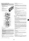
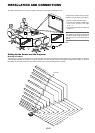
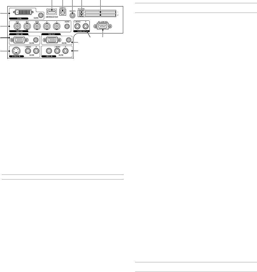
Terminal Panel Features
891013 12
3
2
1
5
6
4
711
5. S-VIDEO IN Connector (Mini DIN 4 Pin)
Here is where you connect the S-Video input from an external source
like a VCR.
NOTE: S-Video provides more vivid color and higher resolution than the tra-
ditional composite video format.
S-VIDEO AUDIO Input Jacks R/L (RCA)
These are your left and right channel audio inputs for stereo sound
from an S-Video source.
6. VIDEO IN Connector (RCA)
Connect a VCR, DVD player, laser disc player, or document camera
here to project video.
VIDEO AUDIO Input Jacks R/L (RCA)
These are your left and right channel audio inputs for stereo sound
from a Video source.
7. AUDIO OUT Jacks R/L (RCA)
You can use this connector to output sound from the currently se-
lected input source (RGB 1, RGB 2, DVI (DIGITAL), Video or S-Video).
Output sound level can be adjusted in accordance with the sound
level of the internal speaker.
8. USB Port (MOUSE/HUB) [Type A]
Connect a USB mouse. You can operate the menu or Viewer with the
USB mouse via this port.
•A USB-supported scanner or PC peripheral can be connected
to this port. (USB Hub Function)
9. USB Port (PC) [Type B]
Connect this port to the USB port (type A) of your PC using the sup-
plied USB cable. You can operate your computer's mouse functions
from the remote control. This port also serves as a PC Control port
by using Dynamic Image Utility 2.0 included on the supplied CD-
ROM.
10. REMOTE (Mini Jack)
Connect your remote control cable here for wired operation.
11. PC CONTROL Port (D-Sub 9 Pin)
Use this port to connect your PC to control your projector via a serial
cable. This enables you to use your PC and serial communication
protocol to control the projector. A commercially available RS232C
cross cable is required to use this port. You can also control the pro-
jector by using Dynamic Image Utility 2.0 included on the supplied
CD-ROM.
To do so you must first have Dynamic Image Utility 2.0 installed on
your PC. If you are writing your own program, typical PC control codes
are on page E-64.
12. PC CARD Slot 1/2
Insert a PC card, commercially available LAN card or NEC optional
wireless LAN card here.
There are two slots: Slot 1 and Slot 2.
NOTE: A dummy card is inserted into each slot at the time of shipment. First
remove the dummy cards before use.
13. PC CARD Eject Button 1/2
Press to eject a PC card partially. Each slot has its own eject button:
1 and 2.