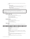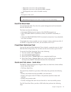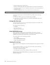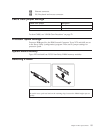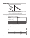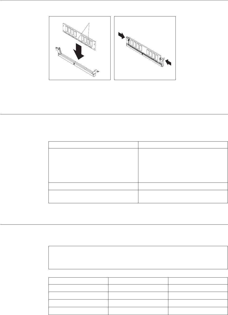
Installing
a
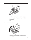
DIMM
Notches
1.
Position
the
DIMM
above
the
connector
so
that
the
two
notches
on
the
bottom
edge
of
the
module
align
properly
with
the
empty
connector.
2.
Firmly
push
the
module
straight
down
into
the
connector
until
the
retaining
clips
pop
up
and
fit
snugly
around
both
ends
of
the
module.
Power
Supply
If
the
power-on
indicator
is
not
on,
the
power-supply
fan
is
not
running,
or
the
computer
will
not
power-off,
do
the
following:
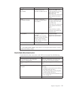
Check/Verify
FRU/Action
Check
the
following
for
proper
installation.
v
Power
Cord
v
On/Off
Switch
connector
v
System
Board
Power
Supply
connectors
v
microprocessor(s)
connection
Reseat
Check
the
power
cord
for
proper
continuity.
Power
Cord
Check
the
power-on
switch
for
continuity
when
pressed.
Power-on
Switch
If
the
above
are
correct,
check
the
following
voltages.
20-pin
main
power
supply
connection
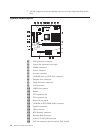
See
“System
board
layout”
on
page
14.
Attention:
These
voltages
must
be
checked
with
the
power
supply
cables
connected
to
the
system
board.
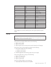
Pin
Signal
Function
1
3.3
V
+3.3
V
dc
2
3.3
V
+3.3
V
dc
3
COM
Ground
4
5
V
+5
V
dc
16
Hardware
Maintenance
Manual


