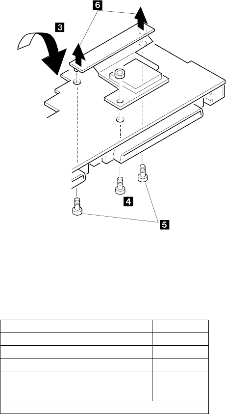
Turn the system board upside down. Remove the screws
4 and 5. Models 370C, 755C and 755Cs have only
the screw on the right side in step 5.
Notes:
1. In step 1, use 5.0 mm and 5.5 mm hex head
screwdrivers. To remove the processor card, gently
lift the area shown by 3 straight up. Do not pull the
other areas.
2. In step 6, pull both edges of the bracket at the
same time. Do not pull the center of the bracket.
Use the following table for reference when replacing parts.
Step Location (Quantity) Length
1 Expansion bus, lower shield (2) Hex head
1 I/O connector, lower shield (6) Hex head
4 Processor card (1) 6 mm
5 Processor card connector
750x - (2), 370C, 755C, 755Cs
- (1)
4 mm
Note: Make sure you use the correct screw.
288 IBM Mobile Systems HMM


