(T)
Note: Signal lines, not used in these steps, are used
for communication between the system and the
battery. The storage switch is used to control the
power to the internal microprocessor of the battery.
The storage switch should be set to off (0) only when
the battery is going to be kept in storage for more
than two months.
3. If the voltage is less than +8.0 V dc, the battery pack
has been discharged or is defective. Recharge the
battery. If the recharging does not work, go to Step 5
to check the charging circuit.
If the voltage is still less than +8.0 V dc after the
recharging, replace the battery.
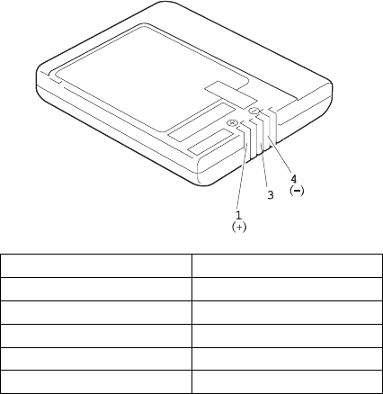
4. If the voltage is more than +8.0 V dc, measure the
resistance between battery terminals 3 and 4. The
resistance must be 4 to 30 K ohm.
If the resistance is not correct, replace the battery
pack.
If the resistance is correct, replace the DC/DC card.
5. To check the charging circuit, do the following. Plug
in the AC Adapter with the battery pack removed,
then power-on the computer.
6. Measure the charging voltage between DC/DC
terminals 1 (+) and 4 (−).
7. If the voltage is less then +9.0 V dc, replace the
DC/DC card. If the voltage is more than +9.0 V dc,
the charging circuit is working correctly, replace the
battery pack.
Terminal Voltage (V dc) / Signal
1 +8.0 to +13.0
2 Send
3 Thermal
4 Ground (−)
5 R1
ThinkPad 755CD, 755CDV (9545) 325


