


Blue or terra-cotta on a part of the hardware indicates a touch point where you can grip the hardware
to remove it from or install it in the system, open or close a latch, and so on. Terra-cotta might also
indicate that the part can be removed and replaced with the system or logical partition power on.
5. Ensure that you have access to a medium flat-blade screwdriver, a Phillips screwdriver, and a pair of
scissors.
6. If parts are incorrect, missing, or visibly damaged, do the following:
v If you are replacing a part, contact the provider of your parts or next level of support.
v If you are installing a feature, contact one of the following service organizations:
– The provider of your parts or next level of support.
– In the United States, the IBM Rochester Manufacturing Automated Information Line (R–MAIL)
at 1–800–300–8751.
In countries and regions outside of the United States, use the following Web site to locate your service
and support telephone numbers:
http://www.ibm.com/planetwide
7. If you encounter difficulties during the installation, contact your service provider, your IBM reseller,
or your next level of support.
8. If you are installing new hardware in a logical partition, you need to understand and plan for the
implications of partitioning your system. For information, see Logical Partitioning.
Identifying a part
Use these instructions to learn how to identify the location of a failed part, the location of a part to be
removed, or the location to install a new part on your system or expansion unit using the appropriate
method for your system.
For IBM Power Systems servers that contain the POWER7 processor, the light-emitting diodes (LEDs) can
be used to identify or verify the location of a part that you are removing, servicing, or installing.
The fault (amber) LED indicates an error and corresponds to the location code in the system reference
code (SRC). The LED is activated and deactivated automatically.
If you need to use the identify function, use the following procedures.
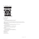
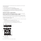
Control panel LEDs
Use this information as a guide to the control panel LEDs and buttons.
The control panel has LEDs that indicate various system status.
36 Power Systems: Power supplies for the 9117-MMB or 9179-MHB