


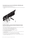

Installing the service access cover on a rack-mounted 8202-E4B or 8205-E6B
system
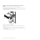
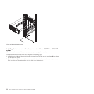
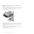
Use this procedure to install the service access cover.
1. Place the service access cover on top of the system, about 25 mm (1 in.) from the upper chassis ledge.
2. Hold the service access cover against the system unit and slide it toward the front of the system. The
tabs of the service access cover slide beneath the upper chassis ledge.
3. Align the two thumbscrews (A) located on the back of the service access cover with the two holes on
the back of the system chassis.
4. Tighten the thumbscrews to secure the service access cover.
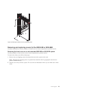
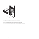
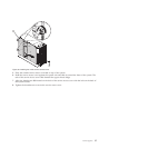
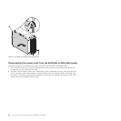
Installing the service access cover on a stand-alone 8202-E4B or 8205-E6B system
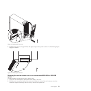
Use this procedure to install the service access cover.
1. Place the inside service access cover (A) on top of the system, about 25 mm (1 in.) from the upper
chassis ledge.
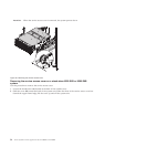
2. Hold the service access cover against the system unit and slide it toward the front of the system. The
tabs of the service access cover slide beneath the upper chassis ledge.
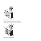
3. Align the two thumbscrews (B) located on the back of the service access cover with the two holes on
the back of the system chassis.
4. Tighten the thumbscrews to secure the service access cover.
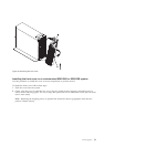
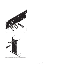
Figure 49. Installing the service access cover
56 Power Systems: Power supplies for the 9117-MMB or 9179-MHB