


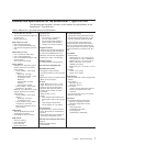
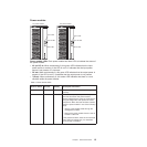
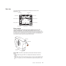
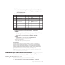

Rear view
This section identifies the components and indicators on the rear of the
BladeCenter T unit.
I/O module 2 I/O module 1
I/O module 4
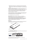
ESD connector
I/O module 3
LAN module
KVM module
Blower module 2
Blower module 4
Blower module 1
Blower module 3
TOP
D
TOP
D
BTM
E
BTM
E
24
13
CRT
MJR
MNR
2
Alarms
1
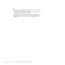
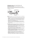
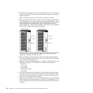
Blower modules
The blower modules are hot-swap units that are installed into the rear of the
system. The BladeCenter T unit comes with four blowers that are in a 3+1
redundancy configuration. All the cooling requirements are met if one blower fails.
All blowers contain a backflow device that prevents the system from drawing air into
the exhaust port of a failed blower. The management module in the BladeCenter T
unit controls the blower speed and detects blower failures.
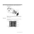
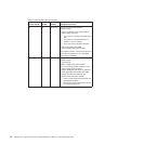
Blower
Error LED
Power LED
Blower LEDs: The LEDs on each blower provide status information about the
blower.
v Power: When this green LED is lit, it indicates that the blower module has
power.
v Error: This amber LED is lit and stays lit when an error has been detected in the
blower. The system error LED on the BladeCenter system-status panels is also
lit.
Chapter 1. General information 15