


Note: The service processor, management module, or systems-management
function must monitor the alarm reset inputs to maintain the fault condition
that you set for the unit. The alarm reset inputs can be voltages in excess
of standard logic levels, so you must electrically or optically isolate them
from the monitoring logic.
Table 4. Alarms connector pinout
Pin # Description I/O Pin # Description I/O
1 Minor alarm reset + I 9 Minor alarm normally
closed
O
2 Minor alarm reset - I 10 Minor alarm common O
3 Major alarm reset + I 11 Major alarm normally open O
4 Major alarm reset - I 12 Major alarm normally
closed
O
5 Critical alarm normally
open
O 13 Major alarm common O
6 Critical alarm normally
closed
O 14 Reserved O
7 Critical alarm common O 15 Reserved O
8 Minor alarm normally open O
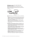
The electrical specifications for the alarms connector are as follows:
– Outputs
- Voltage range: 0 V dc to -100 V dc (maximum current 0.3 A at 100 V dc)
- Current range: 0 A to 1 A (maximum voltage 30 V dc at 1 A)
- Worst-case VA: 1 A at -30 V dc (30 VA maximum) indefinitely
– Inputs
- Voltage range: 0 V dc to -100 V dc (including transients)
- Differential input voltage: 3 V dc to 72 V dc
–
Reset input activation
Pulse width: 200 ms (minimum) to 300 ms
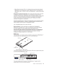
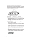
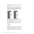
I/O modules
You can install a maximum of four I/O modules at the rear of the system (a
maximum of four Gbit Ethernet switches, or a maximum of two Gbit Ethernet
switches and two Fibre Channel switches). The minimum system configuration
requires one Gbit Ethernet switch or pass-thru module. The I/O switch modules
provide high-performance connectivity between the blade servers.
See the documentation that comes with each I/O module for a description of the
LEDs and connectors on the I/O module.
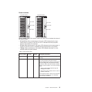
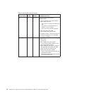
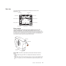
BladeCenter T unit power, controls, and indicators
This section describes the controls and light-emitting diodes (LEDs) and how to
start and shut down the BladeCenter T unit.
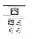
Starting the BladeCenter T unit
Complete the following steps to start the BladeCenter T unit:
1. Read the information in “System reliability considerations” on page 39.
Chapter 1. General information 19