


Before you begin to install options in the BladeCenter T unit, read the following
information:
v Read the safety information beginning on page 113 and the guidelines in
“Handling static-sensitive devices” on page 40. This information will help you
work safely with your BladeCenter T unit and options.
v Blue on a component indicates touch points, where you can grip the component
to remove it from or install it in the server, open or close a latch, and so on.
v Orange on a component or an orange label on or near a component indicates
that the component can be hot-swapped, which means that you can remove or
install the component while the BladeCenter T unit is running. (Orange can also
indicate touch points on hot-swap components.) See the instructions for removing
or installing a specific hot-swap component for any additional procedures that
you might have to perform before you remove or install the component.
v You do not need to disconnect the BladeCenter T unit from power to install or
replace any of the hot-swap modules in the BladeCenter T unit. You need to shut
down the operating system and turn off a hot-swap blade server on the front of
the BladeCenter T unit before removing the blade server, but you do not need to
shut down the BladeCenter T unit itself.
v For a list of supported options for your server, go to http://www.ibm.com/pc/
compat/.
Preparing for system power
There a number of basic differences in preparing for system power between the
Type 8720 (dc power) and Type 8730 (ac power) units.
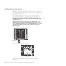
Type 8720 (dc power)
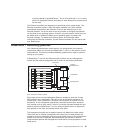
The BladeCenter T unit does not have a power switch. The BladeCenter Type 8720
(dc power) unit has two dc-power terminal connectors each powering two power
modules. The left connection (looking from the rear) supplies power to
power-module bays 2 and 4, while the connection on the right supplies power to
power-module bays 1 and 3.
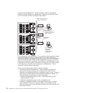
Each dc terminal has four #M6 (1/4 in.) studs, one for -48 V dc, one for RETURN,
and two for connecting the safety ground wire. The following guidelines are
provided for connecting to the -48 V dc power source:
v DC wire rating of 4AWG (7x7x34/36 TC), 105C, 300V UL 10198, CSA approved
and VW1 rated.
v Ring terminal designed for M6 stud, 4AWG wire, wire size (circular Mil area) of
33100-52600, and a wire insulation diameter of 12.8mm to 13.1mm.
Note: The actual wire gauge and ring terminal will be determined by the current
draw and the length of the wire run or as specified by the customer
premises guidelines.
v A two-lug ring terminal is required by NEBS for connecting the single safety
ground wire.
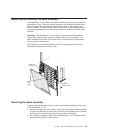
Attention: Remove the power modules before installing the power connections.
Once the power connections are in place, the power modules can be re-installed in
the BladeCenter T unit.
After you connect power to the BladeCenter T unit, all the power-module bays
receive power. The blade servers in the BladeCenter T unit are connected to dc
power but are not turned on. Press the power-control button on the front of each
blade server to obtain full power for the blade server and start its operating system
38 BladeCenter T Type 8720 and 8730: Hardware Maintenance Manual and Troubleshooting Guide