


2. For Type 8720 systems, remove the dc terminal covers and power connections
to each of the dc terminals. For Type 8730 systems, remove each power cord
from the input power connections on the rear of the BladeCenter T unit.
3. Remove the KVM module from the rear of the system (see “Removing the
KVM module” on page 57).
4. Remove the LAN module from the rear of the system (see “Removing the LAN
module” on page 59).
5. Remove the rear panel.
6. Remove the I/O switch or filler that is below the lower flex circuit assembly that
you are removing.
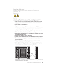
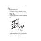
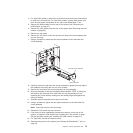
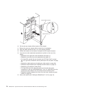
7. Using a screwdriver, loosen the two captive fasteners on the old lower flex
circuit assembly.
Captive fasteners
Lower flex circuit assembly
8. Carefully remove the old lower flex circuit assembly by gripping the top edge of
the assembly and pulling the unit out of the chassis.
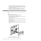
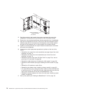
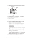
9. Remove the new lower flex circuit assembly from the packaging.
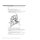
10. Align the assembly so that the stamped position identifier ″BTM″ is facing you,
and position the front end of the new lower flex circuit assembly into the
assembly bay in the chassis, making sure the leading edge rests against the
ceiling of the bay.
11. Carefully push the assembly all the way into the bay.
12. Using a screwdriver, tighten the two captive fasteners on the new lower flex
circuit assembly.
Note: Torque the screws to 8 inch-pounds.
13. Reinstall the I/O switch they you removed.
14. If you have no other replacement procedures to perform at the rear of the
system, re-install the LAN module (see “Installing the LAN module” on page
59) and the KVM module (see “Installing the KVM module” on page 57).
15. For Type 8720, reinstall dc terminal covers.
16. Reconnect the power to the system (see “Starting the BladeCenter T unit” on
page 19).
Chapter 5. Service replaceable units 73