


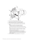
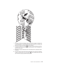
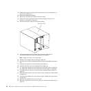

19. Holding the backplane at the top near the guide pins, pull the backplane out
and off of the guide pins.
20. Remove the backplane insulator.
21. Remove the old mechanical chassis, and set it aside.
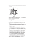
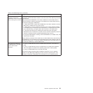
22. Remove the new mechanical chassis from its packaging, and set it into
position to reassemble all the parts.
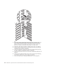
23. Install the backplane insulator into the new chassis.
UP
Mechanical chassis
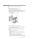
24. Install the backplane on the chassis; then, insert and tighten the six
non-captive screws that mount the backplane to the chassis.
Note: Tighten the screws to 8 inch-pounds.
25. Install the rear chassis stiffner bracket (see page 78).
26. Install the left and right docking board/blower housing assemblies (see page
76).
27. Install the two upper flex circuit assemblies (see page 71).
28. Install the two lower flex circuit assemblies (see page 72).
29. For Type 8720, reinstall the rear dc panel (see “DC Rear Panel” on page 70).
For Type 8730, reinstall the rear ac panel (see “AC rear panel” on page 69).
30. Install the blowers at the rear of the unit (see “Installing a blower module” on
page 55).
31. Install the KVM module at the rear of the unit (see “Installing the KVM module”
on page 57).
32. Install the LAN module at the rear of the unit (see “Installing the LAN module”
on page 59).
33. Install the I/O switches at the rear of the unit.
34. Install the media tray at the front of the unit (see “Installing the media tray” on
page 50).
86 BladeCenter T Type 8720 and 8730: Hardware Maintenance Manual and Troubleshooting Guide