


and remote management station. This is in addition to the IP addresses that are
configured on the management module. You might also have to use the user
interface on the switch module to configure the switch external ports to operate in
the correct link aggregation (trunking) mode, or to configure any VLANs or other
special conditions.
To allow blade servers to communicate with the network, make sure that the
External ports configuration item in the management module is set to Enabled. In
the management-module Web interface, under I/O Module Tasks, click
Management ” Bay n ” Advanced Management ” Advanced Setup and enable
the item (where n is the number of the I/O bay).
To access the user interface using external ports on the switch module, make sure
that the External management over all ports configuration item is set to enabled.
See your network administrator before enabling this feature.
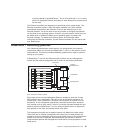
Because all blade servers in the BladeCenter T unit share access to the external
LAN through the switch ports, you can configure the ports on a switch module to
operate together as an aggregate link, or trunk. An aggregate link provides more
bandwidth than a single link to the attached LAN.
Notes:
1. The attaching LAN switch must have a compatible multiport trunk configuration.
2. Configure link aggregation before you attach cables between the external ports
and your LAN equipment.
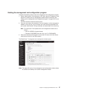
Configure
the switch through the user interface on the switch module, which you
can access through the Web interface to the management module (click I/O
Module Tasks ” Management ” Advanced Management ” Start Telnet/Web
Session in the navigation pane).
Important: For a remote management station, such as a management server, to
communicate with the switch modules in the BladeCenter T unit, the management
port of the switch module must be on the same subnet as the management module.
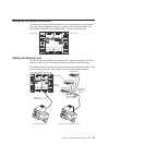
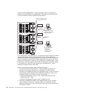
Supporting Ethernet failover
To have the BladeCenter T unit support Ethernet failover on the blade servers, set
up the BladeCenter T unit and blade servers as follows:
1. Configure the Ethernet controllers in one or more blade servers for failover (see
the blade server documentation and the operating-system documentation for
information). When failover occurs on a blade server, the secondary Ethernet
controller takes over network communication, using the I/O module associated
with that controller.
2. Install a switch module or a pass-thru module that is connected to external
Ethernet switches in both I/O-module bays 1 and 2.
3. Configure the Ethernet switch modules and your network infrastructure so that
they can direct traffic to the same destinations.
Configuring the Ethernet controllers in the blade servers
Note: The BladeCenter T unit does not include an Ethernet switch module; this is
an optional feature that must be purchased separately. An Ethernet switch
module or a pass-thru module is connected to an external Ethernet switch
30 BladeCenter T Type 8720 and 8730: Hardware Maintenance Manual and Troubleshooting Guide