


Mechanical chassis
Complete the following steps to replace the mechanical chassis of the BladeCenter
T system.
Note:
v Read “Installation guidelines” on page 37.
v Read the safety notices at ″Safety information″ on page 113.
v Read “Handling static-sensitive devices” on page 40.
1. Shut down the system and remove power from the system (see “Shutting
down the BladeCenter T unit” on page 21).
2. For Type 8720 (dc) systems, remove the dc terminal covers and power
connections to each of the dc terminals. For Type 8730 (ac) systems, remove
each power cord from the input power connections on the rear of the
BladeCenter T unit.
3. Remove the power modules and fillers from the bays at the front of the unit
(see “Removing and installing power modules” on page 46).
4. Remove the management modules and fillers from the bays at the front of the
unit (see “Removing a management module” on page 52).
5. Remove the media tray at the front of the unit (see “Removing the media tray”
on page 50).
6. Remove the server blades and fillers from the front of the unit (see “Removing
a blade server” on page 66).
7. At the rear of the unit, remove the blowers from the docking board/blower
housing assemblies (see “Removing and installing blower modules” on page
54).
8. Remove all I/O switches and switch fillers from the rear of the unit.
9. Remove the KVM module from the rear of the system (see “Removing the
KVM module” on page 57).
10. Remove the LAN module from the rear of the system (see “Removing the LAN
module” on page 59).
11. For a Type 8720 unit, remove the dc terminal covers and the dc rear panel
from the rear of the unit (see “DC Rear Panel” on page 70). For a Type 8730
unit, remove the ac rear panel from the rear of the unit (see “AC rear panel” on
page 69).
12. Remove the two upper flex circuit assemblies (see “Upper flex circuit
assembly” on page 71) and the two lower flex circuit assemblies (see “Lower
flex circuit assembly” on page 72).
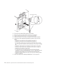
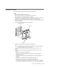
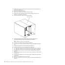
13. For each docking board/blower housing assembly, loosen the two captive
fasteners located above and below the power inlet receptacles (Type 8730) or
dc terminals (Type 8720).
14. Grab the left docking board/blower assembly housing by the frame, and
carefully pull the housing out from the system chassis.
15. Grab the right docking board/blower assembly housing by the frame, and
carefully pull the housing out from the system chassis
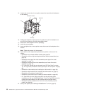
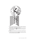
16. Loosen the four captive fasteners on the rear chassis stiffener bracket.
17. Pull the rear chassis stiffener bracket off the chassis.
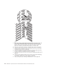
18. Loosen and remove the six non-captive screws that mount the backplane to
the chassis.
Chapter 5. Service replaceable units 85