


3Part 2: DSP-402 Implementation
Section 1
Introduction to the MDrivePlus CANopen DSP-402 Implementation
Introduction
This document describes the Operational Modes and Objects utilized by the MDrivePlus CANopen. The MDrivePlus uses
the CiA DSP402 protocol as described the the CiA document CANopen Device Profile for Drives and Motion Control V2.0B.
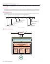
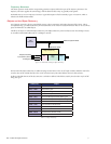
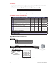
CAN Message Format
The MDrivePlus is compliant with CAN 2.0B Active Specification. The Data Packets follow the message format shown in
Figure 1.1. The Figure is for reference only, please refer to the CAN 2.0B Specification.
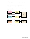
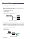
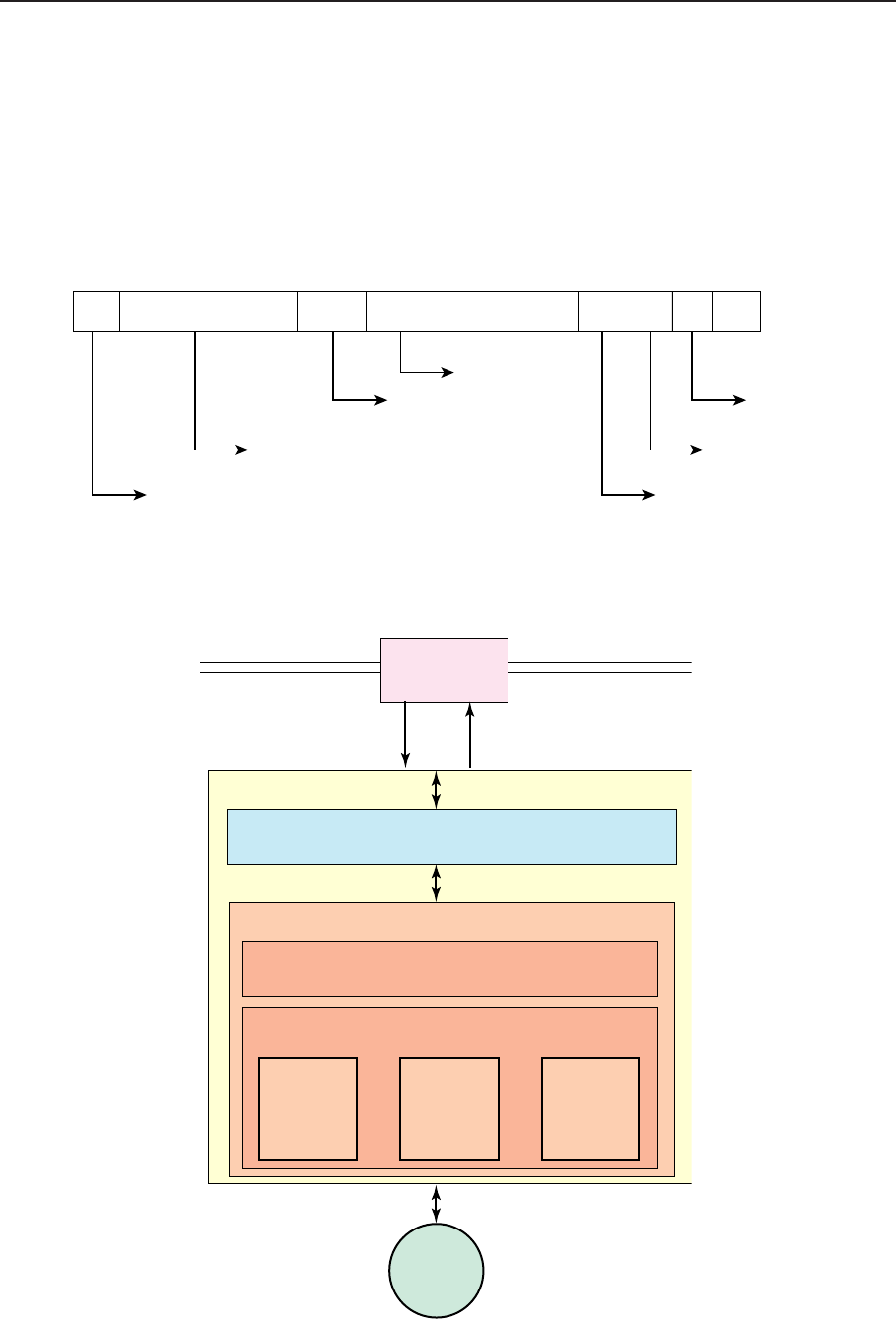
MDrivePlus Architecture
CAN Node
Application Layer and Communications Profile DS 301
Drive Profile DSP 402
Device Control State Machine
(Section XX)
Modes of Operation
Profile
Position
Mode
(Section X)
Homing
Mode
(Section X)
Profile
Velocity
Mode
(Section X)
Motor
MDrivePlus
CAN Network
Figure 1.2: MDrivePlus Architecture
Start
Arbitration
(Command and Address)
Control
Data
CRC ACK End Space
Marks Start
of Message Frame
Marks End
of Message Frame
Address and Message Modifier
(PDO, SDO etc.)
Data Length
Up to 8 Bytes
of Data
Cyclic Redundancy
Checksum
Receiver Pulls
Bit Low
Figure 1.1: Message Format