


36 MDrivePlus CANopen R020507
Functional Description
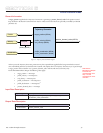
There are two different ways to apply target_positions to a drive, are supported by this device profile.
Set of set-points:
After reaching the target_position the drive unit immediately processes the next target_position which results in a
move where the velocity of the drive normally is not reduced to zero after achieving a set-point.
2. Single set-point:
After reaching the target_position the drive unit signals this status to a host computer and then receives a new set-
point. After reaching a target_position the velocity normally is reduced to zero before starting a move to the next
set-point.
The two modes are controlled by the timing of the bits new_set-point and change_set_immediately in the controlword and
set-point_acknowledge in the statusword.
These bits allow to set up a request-response mechanism in order to prepare a set of set-points while another set still is pro-
cessed in the drive unit. This minimizes reaction times within a control program on a host computer.
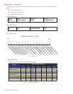
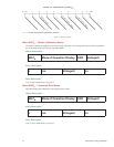
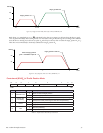
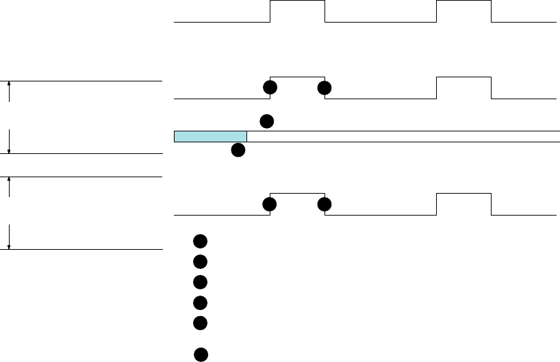
Figure 6.2, Figure 6.3 and Figure 6.4 illustrate the difference between the “set of set-points” mode and the “single set-point”
mode. The initial status of the bit change_set_immediately in the controlword determines which mode is used. Trapezoidal
moves are used as this is the only motion_profile_type the MDrivePlus CANopen supports.
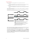
If the bit change_set_immediately is “0” (shaded area in Figure 3.2) a single set-point is expected by the drive
. After data
is applied to the drive, a host signals that the data is valid by changing the bit new_setpoint to “1” in the controlword
. The
drive responds with set-point_acknowledge set to “1” in the statusword
after it recognized and buffered the new valid data.
Now the host may release new_setpoint
and afterwards the drive signals with set-point_acknowledge equal “0” its ability
to accept new data again
. In Figure 3.3 this mechanism results in a velocity of zero after ramping down in order to reach
a target_position X
1
.at T
1
. After signalling to the host, that the set-point is reached like described above, the next target_posi-
tion X
2
is processed at T
2
and reached at T
3
.
1.
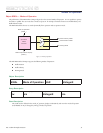
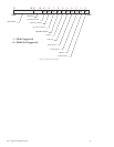
Bit 4: new_set-point
Bit 12: set-point_acknowledge
Bit 5: change_set_immediately
data
0 = Single Set-Point 1 = Set of Set-points
1
6
6
1
5
5
3
3
4
4
2
2
Single Set-Point is Expected by MDrivePlus
Host Signals “Data is Valid” new_set-point = 1
MDrivePlus responds by setting Bit 12, set-point_acknowledge = 1
MDrivePlus responds by setting Bit 12, set-point_acknowledge = 0
MDrivePlus is ready to accept new data
Once Data is Validated, Host may release new_set-point
Indicates state Change of change_set_immediately to 1
ControlWord
(6040h)
StatusWord
(6041h)
Figure 6.2: Set-Point Transmission from Host Computer