


41Part 2: DSP-402 Implementation
Section 7
Homing Mode
General Information
This chapter describes the method by which a drive seeks the home position (also called, the datum, reference point or zero
point). There are various methods of achieving this using limit switches at the ends of travel or a home switch (zero point
switch) in mid-travel, most of the methods also use the index (zero) pulse train from an incremental encoder.
Input Data Description
The user can specify the speeds and the method of homing. There are two homing_speeds; in a typical cycle the faster speed
is used to find the home switch and the slower speed is used to find the index pulse. The manufacturer is allowed some discre-
tion in the use of these speeds as the response to the signals may be Dependent upon the hardware used.
Output Data Description
There is no output data except for those bits in the statusword which return the status or result of the homing process and the
demand to the position control loops.
Internal States
There is only one internal state called homing which is reflected in the bits of the statusword.
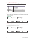
Controlword (6040
h
) of Profile Position Mode
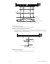
15 9 8 7 6 5 4 3 0
See 1.3 Halt See 1.3 Reserved Homing Operation Start See 1.3
MSB LSB
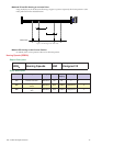
Bit Name Value Description
4
Homing Operation
Start
0 Homing Mode Inactive
0 1 Start Homing Mode
1 Homing Mode Active
1 0 Interrupt Homing Mode
8 Halt
0 Execute the instruction of bit 4
1 Stop motion
Table 7.1: Homing Mode Bits of Controlword
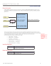
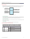
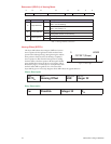
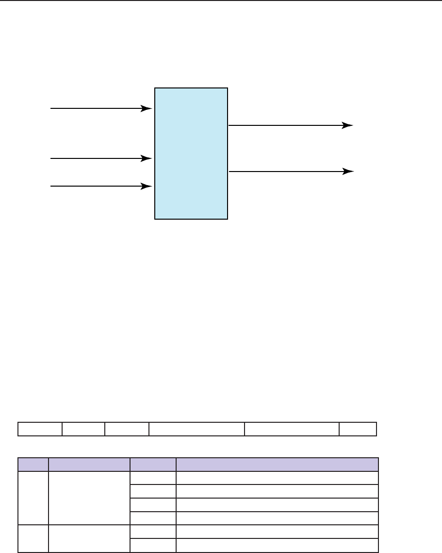
control_word
status_word
position_demand_value
homing_method
homing_speed
Homing
Figure 7.1: The Homing Function